MAP1100 Section-42 Power Control Switch State
Procedure
- Figure 1 is an example
of the details window for the Power Control Switch check.
Figure 1. Window: PowerControl switch details 
- Action:
- For Model 941: At the upper left rear of Rack-1,
observe the Local remote switch card white Local/Remote switch. It
should be in the Remote position (up). It should be in the local position
(down) only if directed by next level of support or an isolation MAP
for the special case where the management console could not control
the storage facility power.
- If the state is displayed as LOCAL, observe the white local remote
switch position.
- If the white switch is in LOCAL (down), complete the service action that had you set it to local. If there is no service action in progress, reset the switch back to REMOTE.
- If the white switch is in REMOTE (up), there is a problem with the physical setting of the switch not agreeing with the setting reported by the code. Call next level of support.
- If the state is displayed as REMOTE, this is correct if the white switch is in the REMOTE (up) position. If the white switch is in the LOCAL (down) position, call the next level of support.
Figure 2. 941 Local remote switch cards 
- If the state is displayed as LOCAL, observe the white local remote
switch position.
-
For Model 951, 961, 98x (not 983): At the upper left
rear of Rack-1, observe the Local remote switch card white Local/Remote switch. It should be in the
Remote position (right). It should be in the local position (left) only if directed by next level of
support or an isolation MAP for the special case where the management console could not control the
storage facility power.
- If the state is displayed as LOCAL, observe the white local remote switch position.
- If the white switch is in LOCAL (left), complete the service action that had you set it to local. If there is no service action in progress, reset the switch back to REMOTE.
- If the white switch is in REMOTE (right), there is a problem with the physical setting of the switch not agreeing with the setting reported by the code. Call next level of support.
- If the state is displayed as REMOTE, this is correct if the white switch is in the REMOTE (right) position. If the white switch is in the LOCAL (left) position, call the next level of support.
Figure 3. 951, 961, 98x (not 983) Local remote switch cards 
- If the state is displayed as LOCAL, observe the white local remote switch position.
-
For Model 983:
- The Local remote switch card (C6) is inside the management enclosure. See Figure 4.
- The Local Mode jumper can only be plugged into the Local Mode connector when the management enclosure is out in the service position and the cover is removed. See Figure 5.
- To install the management enclosure cover, the jumper must be unplugged and placed in the storage bracket. This sets the power state to Remote.
Figure 4. Locations for management enclosure 
Figure 5. Location codes for the local remote switch card (Model 983) 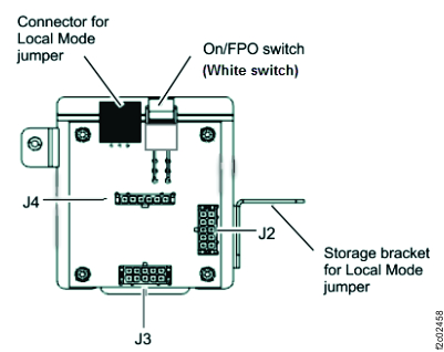 At the front of the rack, slide the management enclosure out to the service position and remove the top cover. See Figure 6.Note: The management enclosure is below the two CEC enclosures.
- Fully loosen the left and right captive thumb screws.
- Slide the management out fully so the sliding rails lock into place.
- At the rear of the top cover, fully loosen the left and right captive thumb screws.
- Slide the cover back until it lifts off.
Figure 6. Management enclosure (front) 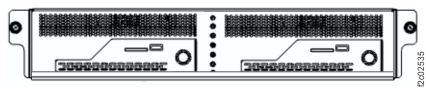 The Local Mode jumper should be in the Local Mode connector if directed by next level of support or an isolation MAP for the special case where the management console could not control the storage facility power.
- If the state is displayed as LOCAL, observe the jumper location.
- If the jumper is in the Local Mode connector, complete the service action that had you set it to local. If there is no service action in progress, unplug the jumper and put it in the storage bracket to set it back to Remote. See Figure 5.
- If the jumper is not in the Local Mode connector, REMOTE, there is a problem with the physical setting of the jumper not agreeing with the setting reported by the code. Call next level of support.
- If the state is displayed as REMOTE, this is correct if the jumper is in the storage bracket. If the jumper is in the LOCAL Mode connector, call the next level of support.
- For Model 941: At the upper left rear of Rack-1,
observe the Local remote switch card white Local/Remote switch. It
should be in the Remote position (up). It should be in the local position
(down) only if directed by next level of support or an isolation MAP
for the special case where the management console could not control
the storage facility power.