Use extension hardware to extend all racks to full height. Populate the extension section
as required.
Procedure
You are installing rack extension hardware. Insert wheel chocks (if available) or temporarily
lower the stabilizer feet to prevent the rack from moving.
At the top of the rack, remove four screws from each side of the top cover. See Figure 1.
Notes:
The top cover is secured with eight long M10 hex head screws. The extension kit includes a 12 mm deep socket for use with the screws. Store the
socket in the document enclosure at the rear of the machine after use.
The top cover is raised in stages to three or more
different stop points at both the front and rear.
When the top cover is at the final stop, the extension panels are installed and secured
to the frame. After the panels are secure, the top cover is lowered and secured to the extension
panels.
Attention: Apply pressure up and down to ensure that the stop latches engage and hold
the top cover at each stop.
Figure 1. Top cover screw locations
Raise the top cover to full extension. See Figure 2 and Figure 3.
Release the four safety locking pins, one at each corner of the rack, by pulling out each pin
and rotating 1/4 turn.
Lift the rear of the top cover to the first stop. Ensure that the safety latches are
engaged.
Note: Use a light up-and-down force on the top cover to confirm that the latches are engaged.
Attention: If the latches do not automatically engage, or the
top cover slips back down, release the safety pins (step 3.a above) only while actively
lifting the cover, and engage the safety pins (step 3.g below) at each stop
Lift the front of the top cover to the first stop. Ensure that the safety latches are
engaged.
Lift the rear of the top cover to the next stop. Ensure that the safety latches are
engaged.
Lift the front of the top cover to the next stop. Ensure that the safety latches are
engaged.
Repeat steps d and e until the top cover is fully extended.
Engage the four safety locking pins by rotating each pin about 1/4 turn until it snaps into the
frame. Ensure that the pins are fully seated.
Figure 2. Top cover safety pin
Figure 3. Lifting the top cover
Install and secure the extension panels. The guide pins on each panel point down. See Figure 4 and Figure 5. The
extension panels and the screws that are used to secure them are described in Table 1.
Note: The rear panels are larger and have a notch for the top cover struts that is closer to the
edge of the panel, compared to the front panels.
Install the front left extension panel. Secure to frame with two screws at front and rear of
panel. Do not tighten the screws at this time.
Install the rear left extension panel. Secure to frame with two screws at front and rear of
panel. Do not tighten the screws at this time.
Install the rear right extension panel. Secure to frame with two screws at front and rear of
panel. Do not tighten the screws at this time.
Install the front right extension panel. Secure to frame with two screws at front and rear of
panel. Do not tighten the screws at this time.
Figure 4. Extension panel pin locations
Note: In Figure 5, screws used to secure panels might be different from screws that are shown in the diagram. See
Table 1.
Figure 5. Extension panel screw locations
Lower the top cover to the top of the extension panels, and secure to the panels. The screws
that are used to secure the top cover are described in Table 1.
They were removed from the top cover at the beginning of this procedure.
Release the four safety locking pins, one at each corner of the rack.
Carefully push down on the rear of the top cover until it rests on top of the rear extension
panels.
Carefully push down on the front of the top cover until it rests on top of the front extension
panels.
Check that the four safety locking pins have latched. Latch manually, if required.
Insert four screws into each side of top panel, leaving them loose. Screw position is at front
and rear of each extension panel.
Tighten the screws that were installed in step 5 to secure the extension panels to the frame.
Alternate between the left and right sides of the frame, in the order shown in Figure 7.
Tighten the screws that were installed in step 6 to secure the top panel to the extension
panels. Alternate between the left and right sides of the top panel, in the order shown in Figure 7. See Figure 6 and Figure 7.
Figure 6. Securing the top panel
Figure 7. Top panel tightening sequence
Note: The fasteners that are used for the remainder of this section of the procedure are described
in Table 2.
Install the storage enclosure rails.
Note: There are up to three sets of rails to install in the extension section, depending on
model.
Install nut clips, if not already present, on the left rear and right rear EIA rails of the
extension panels.
Note: Nut clips are spaced every six holes, following the existing pattern in the storage enclosure
section of the rack. The result is nut clips that are installed on the 3rd, 9th, and 15th holes from
the top of the extension panel. Refer to Table 1.
For all-flash
models 985, 986, 988, 85E, 86E, and 88E install additional nut clips, in top hole and 13th
hole from top, on the left rear and right rear EIA rails of the extension panels.
Notes:
The result for all-flash
models is nut clips that are installed on the 1st, 3rd, 9th, 13th, and 15th holes from the top
of the extension panel. Refer to Table 1.
Leave the nut clips installed in the top hole of the base rack EIA rails, just below the
extension panels.
Insert the left and right side rails from the front of the rack, making sure that the rails
align with the EIA rail holes front and rear.
At the rear of the rack, secure both the left and right rails with the screws provided.
Table 1. Nut clip installation in extension panel EIA rails
Extension panel EIA rail hole (numbered from top)
Standard models
All-flash models
1st (top)
n/a
Install nut clip
3rd
Install nut clip
Install nut clip
9th
Install nut clip
Install nut clip
13th
n/a
Install nut clip
15th
Install nut clip
Install nut clip
Important: In the steps that follow, you install storage hardware (storage enclosures,
high-performance flash enclosures, or microbays) in the extension section of the rack. Each of these
components was packaged separately from the rack you are installing. Take time to identify the
locations of these components.
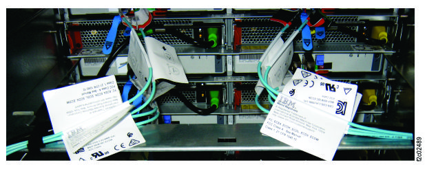
Look for a label that is fastened to the top of the enclosure or
microbay. An identical label is found on the side of the package that contains the enclosure or
microbay. This label contains the rack identification, rack serial number, and component
location.
Example:

A-BOX (rack identification - in this case, A-BOX represents Rack-1)
HGD40 (serial number of Rack-1)
F02   (component location - in this case, F02, which is a high-performance flash
enclosure)
Table 2. Location designations
Label description
Location
A-BOX or RACK-1
Rack-1
B-BOX or RACK-2
Rack-2
C-BOX, C1-BOX, or RACK-3
Rack-3
D-BOX, C2-BOX, or RACK-4
Rack-4
E-BOX, C3-BOX, or RACK-5
Rack-5
Mxx (for example, M02)
Microbay location Mxx
Fxx (for example, F02)
HPFE location Fxx
Gxx (for example, G02)
Storage enclosure location Gxx
Are you installing Rack-1 of an all-flash model 985, 986, or 988?
You are installing an all-flash Rack-1. Move the cable brackets (cable retention bars), with cables
attached, to their operating locations.
Note:
Rack-1 of a model 988 or model 986 all-flash has two cable brackets at the top of the storage
enclosure rails at EIA location 40.
Rack-1 of a model 985 all-flash has only one bracket at that location.
Move the upper cable bracket (if provided) from its location above the storage enclosure
rails at EIA location 40 to the top of EIA location 46.
Secure the bracket to the nut clips you installed at the 1st hole at the top of the extension
panel (above the storage enclosure rails at EIA location 46).
The cable labels that are associated with this bracket are shown in Table 3.
Move the lower cable bracket from its location at the top of the storage enclosure rails
at EIA location 40 to the top of EIA location 42
Secure the bar to the nut clips you installed at the 13th hole down from the top of the
extension panel (above the storage enclosure rails at EIA location 42).
The cable labels that are associated with this bracket are shown in Table 3.
Table 3. Microbay and storage enclosure cable labels
Model
Power cables (if attached) are labeled for connection to
SAS cables (if attached) are labeled for connection to
upper bracket
(top of 46U)
lower bracket
(top of 42U)
upper bracket
(top of 46U)
lower bracket
(top of 42U)
985 all-flash
none
M06-C1, C2
none
M06, F05, F06
986 all-flash
M06-C1, C2
M08-C1, C2
M06, F05, F06
M08, F07, F08
988
M02-C1, C2
M04-C1, C2
M02, F01, F02
M04, F03, F04
For all-flash model 986 or 988, install the microbay tray (shipped separately, with the storage
enclosures) at the rear of the storage enclosure rails at EIA locations 43-44.
Notes:
You will always install a microbay tray at this location in all-flash model 988.
You will install a microbay tray at this location in all-flash model 986 if you have flash
enclosures to install in EIA locations 43-46 (F05 and F06).
You will not install a microbay tray at this location in other models.
Microbays are installed in this tray when flash enclosures are present at EIA locations 43-46
Remove the microbays (if present) from the tray before installing.
Important: microbays must be installed in their original locations from manufacturing, as
designated on SAS and PCIe cable labels.
Leave SAS and PCIe cables attached to the microbays.
Note which microbay is C1 and which is C2. The cable labels show these locations.
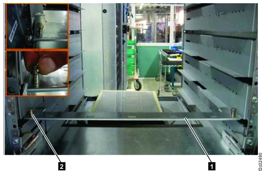
Press the release tabs 1 toward the center of each microbay. See
Figure 10.
Slide each microbay back. Release the service latches 2 and
3 , as needed, and remove the microbay.
At the rear of the rack, install the microbay tray.
Note: See Figure 10. The
microbays are installed into the rear end of the tray.
Note the flange that extends outward on either side of the microbay tray, about 7 cm from the
front end of the tray.
Lift the tray so the side flange is above the rear mounting flange of the storage enclosure
rail. This fits the tray between the rail you are fastening it to, and the rail above it.
Slide the tray in until the tray flange passes the rail flange.
Lower the tray and slide into place against the stop pins in the storage enclosure rails.
Secure with screws to the bottom hole of each storage enclosure rail.
At the
front of the rack, install the storage enclosures.
Notes:
This includes both high-performance flash enclosures and FC-AL attached
storage enclosures.
Storage enclosure components must be removed to meet single-person lifting limits. All
components must be labeled before you remove them, and must be reinstalled in their original
locations from manufacturing.
Label and remove all drives from each storage enclosure.
Label and remove the FCICs or ESMs from the rear of each storage enclosure.
Label and remove the power supplies from the rear of each storage
enclosure.
Install each storage enclosure in its correct location. At the front of
the rack, secure to frame at the lower left and lower
right of each enclosure with the screws provided.
Reinstall the power supplies, FCICs or ESMs, and drives in their
original location in each storage enclosure.
Install the decorative bezels (packaged with the enclosure) at the left front of the
enclosure.
At the front of the rack, install storage enclosure fillers in any empty storage enclosure
locations.
At the rear of the rack, install the cable brackets on the rails in extension section storage
enclosure locations.
For systems with FC-AL/SAS storage enclosures
that are installed in the extension section, route and connect cables.
Route and connect the FC-AL cables to the storage enclosure FCICs.
Route and connect the power cables to the storage enclosure power supplies.
For model 88E Rack-2, at the rear of the rack, if additional high-performance flash enclosures
were installed in the extension section (EIA locations 39 to 46), route and connect the SAS cables
to the high-performance flash enclosure ESMs. The cables are grouped by ESM location (C1 or C2).
Routing is shown in Figure 9.
Cables are routed to the cable bracket from the upper and lower enclosure of each enclosure
pair.
Cables attached to the left ESM (Fxx-C1) of each enclosure are routed to the left side of the
bracket, then down to the cable bracket at EIA location 40.
Continue routing the cables across the cable bracket at EIA location 40 to the rack-to-rack
access hole at the right rear of the rack.
Cables attached to the right ESM (Fxx-C2) of each enclosure are routed to the right side of the
bracket, then down to the rack-to-rack access hole at the right rear of the rack.
Figure 9. SAS cable routing
For systems (other than model 88E Rack-2) with SAS flash
enclosures (High-Performance Flash Enclosure Gen2) installed in the extension section, install
microbays (if present), route, and connect cables.
Route and connect the power cables to the flash enclosure power supplies.
Install microbays (if present) into the lower microbay tray at EIA location 39 (M02, M04, or
M08). See Figure 10.
Release the service latches 2 and 3 ,
as needed, to insert the microbay.
Ensure that the release tabs 1 latch into the microbay tray.
Install microbays (if present) into the upper microbay tray at
EIA location 43 (M02 or M06). See Figure 10.
Release the service latches 2 and
3 , as needed, to insert the microbay.
Ensure that the release tabs 1 latch into the microbay tray.
Route and connect the SAS cables between the flash enclosures and the associated microbays.
Refer to the cable labels, Figure 11 and Figure 12.
A slight force might be required to latch the connectors.
Route and connect the power cables to microbays, if installed. Refer to the cable labels and Figure 11.
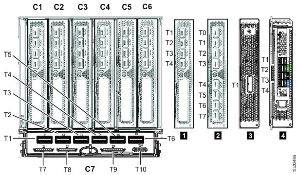
Route and connect the PCIe cables between the I/O enclosures (ports XIx-P1-C7-T5 and T6) and microbays (ports
Mxx-Cx-T7), if installed. Refer to the cable
labels, Figure 11 and Figure 13.
Note: Viewed from the rear of the rack.
Figure 10. Microbays C1 (left, in operating position) and C2 (right, in service position)
Repeat steps 1 through 17 for any expansion racks
with rack extension hardware.
Install the left side (viewed from the front) extension panel cover over the extension panels
in Rack-1 and secure top with the M4 screws that are provided.
Figure 15. Installing the extension panel cover
Does the storage facility that you are installing have one or more expansion racks?
No, it is a Rack-1 with no expansion racks. Continue to step 21.
The storage facility has no expansion racks. Install the right side (viewed from the front)
extension panel cover over the extension panels and secure top with the M4 screws that are
provided.
 Note: The fasteners that are used for the remainder of this section of the procedure are described in Table 2.