Positioning the expansion racks
Procedure
-
Determine the position of each expansion rack to be installed to this Rack-1.
-
Use each expansion rack number label to ensure that the expansion rack is for this Rack-1. The
label is at the left side of the rack, behind the front door, below the upper door hinge. The
expansion rack label must list the correct Rack-1 serial number.
Attention: This storage facility installation will fail if an expansion rack is for a different Rack-1. If the Rack-1 serial numbers do not match, stop the installation and call the next level of support.
Figure 1. Rack serial number and rack number labels (Models 98x, 8xE) Note: Rack-4 and Rack-5 not shown. Some models do not use a Rack-3.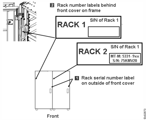
-
Use each expansion rack number label to ensure that the expansion rack is for this Rack-1. The
label is at the left side of the rack, behind the front door, below the upper door hinge. The
expansion rack label must list the correct Rack-1 serial number.
-
Install side trim pieces with gaskets on right side of Rack-1 at top, bottom, front, and rear.
See Figure 2. The screws that are used to secure the trim pieces to the racks
are described in Table 3.
Note: Each trim piece can come in one or two parts. Refer to Table 3.
-
Install the top and bottom trim pieces and secure with screws. Top piece gasket
1 goes up, bottom piece gasket 2 goes
down. See Figure 3.
Figure 2. Trim piece screw locations, right side of rack Note: Extension panels not shown.
Figure 3. Trim piece detail, right side of rack Note: Rack-4 and Rack-5 not shown
-
Install the top and bottom trim pieces and secure with screws. Top piece gasket
1 goes up, bottom piece gasket 2 goes
down. See Figure 3.
-
Install side trim pieces (without gaskets) on left side of Rack-2 at front and rear. See Figure 4.
Notes:
- Left side trim pieces (without gaskets) are front and rear only, there are no top or bottom pieces.
- Each trim piece can come in one or two parts. Refer to Table 3.
- Install front and rear trim pieces and secure with screws. Each screw location has two holes. Insert the screw into the smaller hole.
- For models with extension panels, install trim pieces (without gaskets) on the left front and left rear extension panels.
Figure 4. Trim piece screw locations, left side of rack Note: Extension panels not shown.
-
Roll the expansion rack being installed into position.
- Move the rack outriggers to stowed (operating) position for final positioning of each rack.
- To move each outrigger, pull down on the release handle 2 located under the outrigger, and push the outrigger in. See Figure 5.
Figure 5. Outrigger clamp 
-
Fasten Rack-2 to Rack-1. The screws and washers that are used to fasten the racks together
are described in Table 3 and Table 4.
-
Extension panels (if present) are fastened by using one additional screw with washer in the front and one
additional screw with
washer in the rear.
Note: Suggested method is to install screws working top to bottom at rear, then top to bottom at front. You must partially lower the left front stabilization foot of Rack-2 to insert the bottom screw.
Figure 6. Fastener positions, rear of Rack-2 Note: Front fastener positions are similar
Figure 7. Screw and washer detail (example), rear of Rack-2 
-
Extension panels (if present) are fastened by using one additional screw with washer in the front and one
additional screw with
washer in the rear.