I/O enclosure (2U) LED indicators (Model 983)
This section contains FRUs that have LED indicators. Each listed assembly is shown with a description of its LEDs. Do not use LEDs as a starting point for diagnosing a problem.
I/O enclosure (2U) FRUs with LEDs
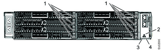
I/O enclosure (2U) front
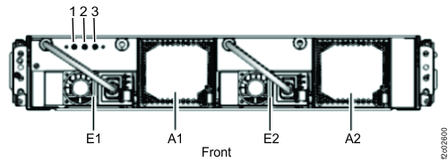
| Index | LED function | Location | Color | LED Off | LED On | LED Flash |
|---|---|---|---|---|---|---|
| 1 |
Enclosure power |
N/A | Green | Power off | Power on | Power standby |
| 2 |
Enclosure identify |
N/A | Blue | Normal | Identify | N/A |
| 3 |
FRU identify for I/O enclosure midplane |
P1 | Amber | Normal | N/A | Identify |
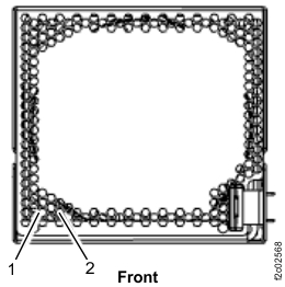
| Index | LED Function | Location | Color | LED Off | LED On | LED Flash |
|---|---|---|---|---|---|---|
| 1 | Power for I/O enclosure fan | A1, A2 | Green | Power off | Power on | N/A |
| 2 | Identify for I/O enclosure fan | A1, A2 | Amber | Normal | N/A | Identify |
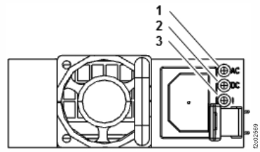
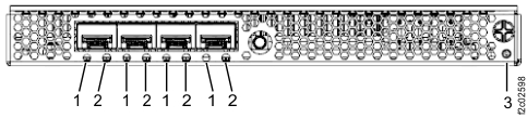
| Index | LED Function | Location | Color | LED Off | LED On | LED Flash |
|---|---|---|---|---|---|---|
| 1 | Input power for I/O enclosure power supply | E1, E2 | Green | No input | Input good | N/A |
| 2 | Output power for I/O enclosure power supply | E1, E2 | Green | Standby off | Output on | Standby |
| 3 | Identify for I/O enclosure power supply | E1, E2 | Amber | Normal | N/A | Fast = identify; slow = com fail |
I/O enclosure (2U) rear
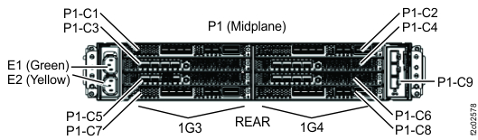
| Index | LED Function | Location | Color | LED Off | LED On | LED Flash |
|---|---|---|---|---|---|---|
| 1 | Slot identify Adapter (if present) identify |
C1 - C8 | Amber | Normal | N/A | Identify |
| 2 | I/O enclosure identify | N/A | Blue | Normal | Identify | N/A |
| 3 | Adapter (PCN) power | P1-C9 | Green | Power off | Power good | N/A |
| 4 | Adapter (PCN) identify | P1-C9 | Amber | Normal | N/A | Identify |
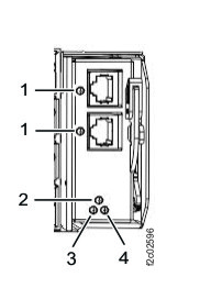
| Index | Left LED | Right LED | State |
|---|---|---|---|
| 1 (Left LED) 2 (Right LED) |
Off | On, green | 4 Gb/s FC link rate - no I/O |
| Fast flash, green | 4 Gb/s FC link rate - active I/O | ||
| On, green | Off | 8 Gb/s FC link rate - no I/O | |
| On, green | 16 Gb/s FC link rate - no I/O | ||
| Fast flash, green | Off | 8 Gb/s FC link rate - active I/O | |
| Fast flash, green | 16 Gb/s FC link rate - active I/O |
| Index | Left LED | Right LED | State |
|---|---|---|---|
| 1 (Left LED) 2 (Right LED) |
Off | Off | Power off |
| On, red | Off | POST failure | |
| On, red | Firmware fault | ||
| Slow flash, white | Slow flash, white | Power on, firmware not initialized or hardware reset | |
| Slow flash, green | Slow flash, green | Link down |
| Index | LED | State |
|---|---|---|
| 3 | Off | Normal |
| On, amber | N/A | |
| Flash, amber | Adapter (slot) identify |
Note: Fully populated adapter shown. LEDs are similar for all adapter versions.
| Index | Location | Color | LED function | LED Off | LED On | LED Flash |
|---|---|---|---|---|---|---|
| 1 | P1-Cx-T5, P1-Cx-T6 (x = 1, 2, 7, 8) |
Green | PCIe link status | Link bad | Link good | N/A |
| Amber | PCIe port identify | Normal |
N/A |
Identify | ||
| 2 | P1-Cx-T7 (x = 1, 2, 7, 8) |
Green | Link status | Link bad | Link good | N/A |
| Amber | Port identify | Normal | N/A | Identify | ||
| 3 | P1-Cx (x = 1, 2, 7, 8) |
Green | Adapter power | Power off | Power on | Power standby |
| 4 | P1-Cx (x = 1 through 8) |
Amber | Slot identify Adapter (if present) identify |
Normal | N/A | Identify |
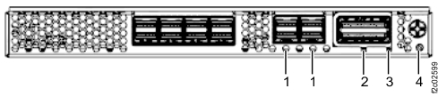
| Index | LED Function | Location | Color | LED Off | LED On | LED Flash |
|---|---|---|---|---|---|---|
| 1 | Adapter (PCN) link status Adapter (PCN) port identify |
P1-C9-T1, P1-C9-T2 |
Green | Link bad | Link good | N/A |
| Amber | Normal | N/A | Identify | |||
| 2 | I/O enclosure identify | N/A | Blue | Normal | Identify | N/A |
| 3 | Adapter (PCN) power | P1-C9 | Green | Power off | Power good | N/A |
| 4 | Adapter (PCN) identify | P1-C9 | Amber | Normal | N/A | Identify |