Rack power and cooling LED indicators (Model 983)
This section contains storage system power and cooling FRUs that have LED indicators. Each listed assembly is shown with a description of its LEDs. Although LED indicators might indicate a failure, do not use them as a starting point for a repair. Display and repair related open serviceable events.
Power and cooling FRUs with LEDs
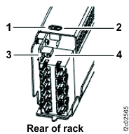
LEDs on the Local remote switch card
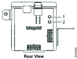
| Index | LED function | Color | LED off | LED on | LED flash |
|---|---|---|---|---|---|
| 1 | Identify | Amber | Normal | N/A | Identify |
| 2 | Power good | White or green | N/A | Powered on | N/A |
LEDs on the management enclosure front panel
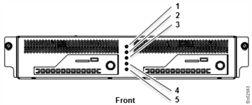
| Index | LED function | Color | LED off | LED on | LED flash |
|---|---|---|---|---|---|
| 1 | Management enclosure status | Green | Powered off | Powered on | N/A |
| 2 | Line cord 1 UPS status | Green | 1 | 2 | 3 |
| 3 | Line cord 2 UPS status | Green | 1 | 2 | 3 |
| 4 | Management enclosure identify | Blue | N/A | Identify | N/A |
| 5 | System attention, system identify | Amber | N/A | System attention 4 | System identify 5 |
|
Notes:
|
|||||
LEDs on the management enclosure power supply
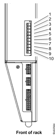
| Index | LED function | Color | LED off | LED on | LED flash |
|---|---|---|---|---|---|
| 1 | +12V Main good, management enclosure power supply. | Green | N/A | Power good | N/A |
| 2 | Power good to RPC1 card, C1. | Green | N/A | Power good | N/A |
| 3 | Power good to RPC2 card, C2. | Green | N/A | Power good | N/A |
| 4 | Power good to primary management console (MC1). | Green | N/A | Power good | N/A |
| 5 | Power good to secondary management console (MC2). | Green | N/A | Power good | N/A |
| 6 | Power good to Ethernet switch SW1 (upper). | Green | N/A | Power good | N/A |
| 7 | Power good to Ethernet switch SW2 (lower). | Green | N/A | Power good | N/A |
| 8 | Power good to intake impeller of fans A1 and A2. | Green | N/A | Power good | N/A |
| 9 | Power good to exhaust impeller of fans A1 and A2. | Green | N/A | Power good | N/A |
| 10 | Identify, management enclosure power supply. | Amber | N/A | N/A | Identify |
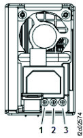
| Index | Label | LED function | Color | LED off | LED on | LED flash |
|---|---|---|---|---|---|---|
| 1 | ! | Power supply error and identify | Amber | Normal | Fault | Identify |
| 2 | DC | Power supply DC good | Green | Standby off | On | Standby |
| 3 | AC | Power supply input good | Green | No input | Input good | N/A |
LEDs on the RPC card
| Index | LED function | Color | LED off | LED on | LED flash |
|---|---|---|---|---|---|
| 1 | Identify | Amber | Normal | See Note 1. | Identify |
| 2 | Operational | Green | Fenced, not booted, or no input power | Operational | N/A |
| 3 | Status 0 | Green | Not for field use. | ||
| 4 | Status 1 | Green | |||
|
Notes:
|
|||||
LEDs on the UPS
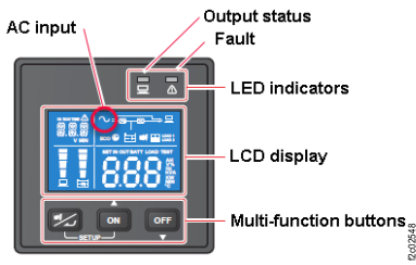
| Index | LED function | Color | LED off | LED on | LED flash |
|---|---|---|---|---|---|
| N/A | Output status | Green | Output off | Output on | N/A |
| N/A | Fault | Red | Normal | Internal or environmental fault |
|
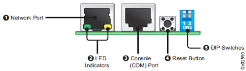
| Index | LED function | Color | LED off | LED on | LED flash |
|---|---|---|---|---|---|
| 2 | Network connection status | Green |
Off Not connected to a network |
On Network connection established and the IPv4 address is usable. |
Flashes slowly (every 500 ms): Faulty IP address. |
| 2 | Linking status between the SNMP IPv6 and the UPS | Yellow | N/A | N/A |
|
| 2 | Status of SNMP IPv6 initializing or upgrading firmware. The two LED indicators flash simultaneously to show its status. |
N/A | N/A | N/A |
|