This section contains FRUs that have LED indicators. Each
listed assembly is shown with a description of its LEDs. While CEC enclosure LED indicators
might indicate a failure, do not use them as a starting point for
a repair.
Table 1. List of CEC enclosure assemblies with LEDs
Assembly
Reference
Control panel assembly
Figure 1
CEC enclosure LEDs, rear
view Figure 2
CEC enclosure , PCIe adapter
slot LEDs Figure 3
Power supply LEDs
Figure 4
CEC enclosure front
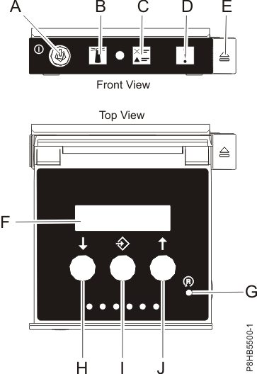
LED indicatorsFigure 1. CEC enclosure control
panel assembly (Models 98x) Table 2. Interpreting
the LEDs on the CEC enclosure control panel assembly
Index
LED Function
Color
LED Off
LED On
LED Flash
A
Power
Green
No power
Full power
Standby power1 (FSP function
running)
B
Identify
Blue
Normal
Identify
N/A
C
System information
Amber
Normal
Requires attention
N/A
D
Enclosure fault roll-up light
Amber
Normal
Fault
N/A
F
Function/Data display
Notes:
During CEC power-on, there is approximately a 30-second transition
period between flashing to solid when the LED might flash faster.
Table 3. Interpreting the CEC enclosure enclosure
disk drive LEDs
Index
LED Function
Color
LED Off
LED On
LED Flash
Upper LED
Disk drive activity
Green
Not active
Activity
Activity
Lower LED
Disk drive fault / identify
Amber
Normal
Fault
Identify
CEC enclosure top
LED indicatorsTop LED indicators are not visible on this
model. Power is not available to the CEC enclosures when they are
in the service position.
CEC enclosure rear
LED indicatorsFigure 2. CEC enclosure rear LEDs
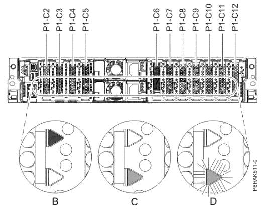
Figure 3. CEC enclosure PCIe adapter slot locations and LEDs (rear view) (model 980)
Table 4. Interpreting the LEDs on the rear
of the CEC enclosure
Index
Figure
LED Function
Color
LED Off
LED On
LED Flash
1
Figure 2 CEC enclosure ID
Blue
Normal
N/A
Identify
2
Figure 2 System information / Attention
Amber
Normal
Attention
N/A
3
Figure 2 CEC enclosure fault
Amber
Normal
Fault
N/A
B
Figure 3 PCIe slot power (activity)
Green
Power off
Normal
N/A
C, D
Figure 3 PCIe slot error and identify
Amber
Normal
Error
Identify
N/A
N/A
Ethernet Link
Green
Not connected
Connected
N/A
N/A
N/A
Ethernet Tx/Rx
Green
Not active
Active
Active
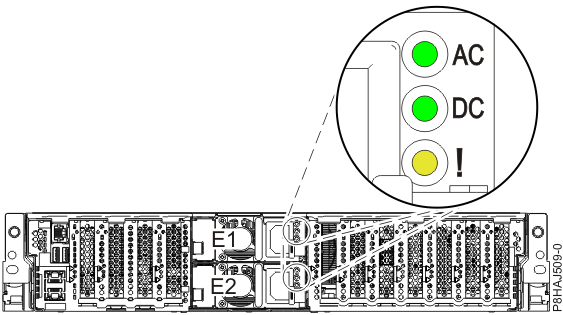
Power supply LED indicators Figure 4. Location of the power supplies and LEDs (Models 980, 983 , 984 )
Table 5. Interpreting the power supply LEDs
Index
LED Function
Color
LED Off
LED On
LED Flash
AC
Power supply input good
Green
No input
Input good
N/A
DC
Power supply DC good
Green
Standby off
On
Standby
!
Power supply error and identify
Amber
Normal
Fault
Identify