This section contains FRUs that have LED indicators. Each
listed assembly is shown with a description of its LEDs. Do not use
LEDs as a starting point for diagnosing a problem.
I/O enclosure FRUs with LEDs
Table 1. List of I/O enclosure assemblies with LEDs
Assembly
Reference
I/O enclosure (front)
Figure 1
I/O enclosure (rear) with Fibre Channel host card,
4 Gb/s
Figure 2
Fibre channel host card, 8 Gb/s (4-port only)
Figure 3
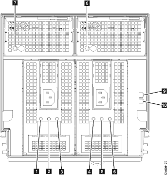
Figure 1. LEDs on the I/O enclosure (front)
Table 2. Interpreting the LEDs on the I/O enclosure (front)
Index
LED Function
Location
Color
LED Off
LED On
LED Flash
1
Input power for I/O enclosure power supply
E1
green
no input
input good
n/a
2
Output power for I/O enclosure power supply
E1
green
standby off
output on
standby
3
Identify for I/O enclosure power supply
E1
amber
normal
n/a
fast = identify, slow = com fail
4
Input power for I/O enclosure power supply
E2
green
no input
input good
n/a
5
Output power for I/O enclosure power supply
E2
green
standby off
output on
standby
6
Identify for I/O enclosure power supply
E2
amber
normal
n/a
fast = identify, slow = com fail
7
Identify for I/O enclosure fan
A1 amber
normal
n/a
identify
8
Identify for I/O enclosure fan
A2
amber
normal
n/a
identify
9
Identify for I/O enclosure
P1
blue normal
identify n/a
10
Power for I/O enclosure
P1
green
power off
power on
standby
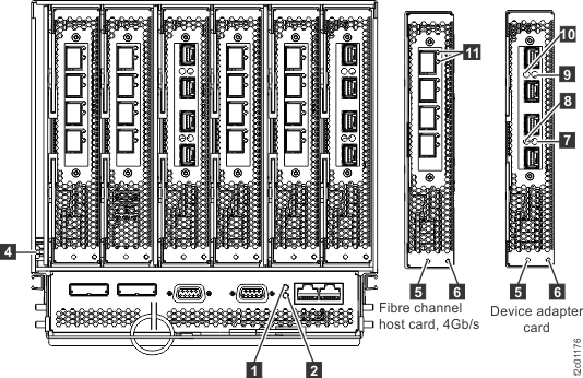
I/O enclosure rear Figure 2. LEDs on the I/O enclosure (rear), with Fibre channel host card, 4 Gb/s
Table 3. Interpreting the LEDs on the I/O
enclosure (rear)
Index
LED Function
Location
Color
LED Off
LED On
LED Flash
1
Power for I/O enclosure PCIe switch
card
P1-C7
green
power off
power on
power standby
2
Identify for I/O enclosure PCIe switch
card
P1-C7
amber
normal
fault
identify
3
Power for I/O enclosure
P1
green
power off
power on
n/a
4
Identify for I/O enclosure
P1
blue
normal
n/a
identify
5
Power for I/O enclosure PCI card
P1-Cx
green
power off
power on
standby (card regulators off)
6
Identify for I/O enclosure PCI slot
P1-Cx
amber
normal
n/a
identify
7
Activity for I/O enclosure device adapter
card
P1-Cx-T3/4
green
Note 1
Note 2
Note 3
8
Identify for I/O enclosure device adapter
card
P1-Cx-T3/4
amber
normal
n/a
identify
9
Activity for I/O enclosure device adapter
card
P1-Cx-T1/2
green
Note 1
Note 2
Note 3
10
Identify for I/O enclosure device adapter
card
P1-Cx-T1/2
amber
normal
n/a
identify
11
Fibre channel port,
4Gb/s, LEDs (see Table 5 and Table 6 )
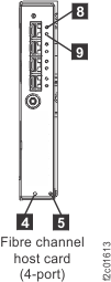
Notes:
LED off indicates port above and port below LED are both
not Ready .
LED on solid indicates port above and port below LED
are both Ready (operational).
If LED is blinking 0.75 sec ON and 0.25 sec OFF, then
only the port above the LED is Ready .
Figure 3. LEDs on Fibre channel host
card, 8 Gb/s (4-port only)
Table 4. Interpreting the
LEDs on the Fibre channel host card 8 Gb/s
Index
LED Function
Location
Color
LED Off
LED On
LED Flash
4
Power for I/O enclosure PCI slot
P1-Cx
green
power off
power on
standby (card regulators off)
5
Identify for I/O enclosure PCI slot
P1-Cx
amber
normal
n/a
identify
8, 9
Fibre channel host card port LEDs (see Table 5 and Table 6 )
P1-Cx-Ty
Fibre
channel host card (4 Gb/s or 8 Gb/s) port
LEDs Table 5 and
Table 6 provide detailed
information on
Fibre Channel host
card port LEDs.
Note: Do not use visual symptoms to replace the host
adapter cards. Only replace them when they are:
Listed in a serviceable event FRU list, OR
Isolated in an isolation procedure MAP
Table 5. Fibre channel host card (4 and 8 Gb/s) port LEDs (normal conditions)
Adapter
Yellow LED
Green LED
State
8-Gb/s adapters (4-port only, Figure 3 )
Off
Slow blink
Normal - link is down or not started
2 blinks
On
2-Gb/s link rate - normal, link is up
3 blinks
On
4-Gb/s link rate - normal, link is up
4 blinks
On
8-Gb/s link rate - normal, link is up
4-Gb/s adapters (Figure 2 )
Off
1 blink/second
Normal: link is down or not started
1 blink
On
1-Gb/s link rate - link is active
2 blinks
On
2-Gb/s link rate - link is active
3 blinks
On
4-Gb/s link rate - link is active
Table 6. Fibre
channel host card (4 Gb/s or 8Gb/s) port
LEDs (Power up, failure, download, or test conditions)
Adapter
Yellow LED
Green LED
State
All
Off
Off
Wake-up failure (board is not responding)
On
Failure when functioning
On
Off
POST failure (board is not responding)
On
Failure when functioning
1 blink/second
Off
Wake-up failure monitor
1 blink/second
Offline (download in progress)
4 blinks/second
Off
POST failure
1 blink/second
Restricted offline mode (a restart is pending)
Irregular blinks
Off
POST process in progress
1 blink/second
Restricted offline mode (test is ongoing)