Positioning the expansion rack
Procedure
-
Determine the position of each expansion rack to be installed to this storage facility.
-
Use each expansion rack number label to ensure the expansion rack is for this the storage
facility. The label is located at the left side of the rack, behind the front door, below the upper
door hinge. The expansion rack label must list the correct the storage facility serial number.
Figure 1. Rack serial number and rack number labels (Models 98x, 8xE) Note: Rack-4 and Rack-5 not shown. Some models do not use a Rack-3.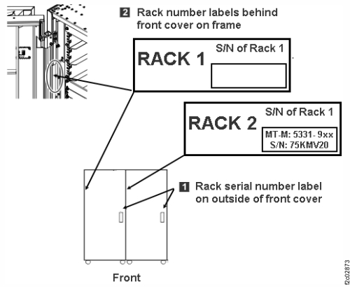 Note: In the steps that follow, "expansion rack" refers to the expansion rack you are installing, while "storage facility" refers to the existing storage facility including any expansion racks already installed.
-
Use each expansion rack number label to ensure the expansion rack is for this the storage
facility. The label is located at the left side of the rack, behind the front door, below the upper
door hinge. The expansion rack label must list the correct the storage facility serial number.
-
Install side trim pieces with gaskets on right side of the storage facility at top, bottom,
front, and rear. See Figure 2. The screws that are used to secure the trim
pieces to the racks are described in Table 7.
Note: Each trim piece can come in one or two parts. Refer to Table 7.
-
Install the top and bottom trim pieces and secure with screws. Top piece gasket
1 goes up, bottom piece gasket 2 goes
down. See Figure 3.
Figure 2. Trim piece screw locations, right side of rack Note: Extension panels not shown.
Figure 3. Trim piece detail, right side of rack Note: Rack-4 and Rack-5 not shown
-
Install the top and bottom trim pieces and secure with screws. Top piece gasket
1 goes up, bottom piece gasket 2 goes
down. See Figure 3.
-
Install side trim pieces (without gaskets) on left side of the expansion rack that you are
installing at front and rear. See Figure 4.
Notes:
- Left side trim pieces (without gaskets) are front and rear only, there are no top or bottom pieces.
- Each trim piece can come in one or two parts. Refer to Table 7.
- Install front and rear trim pieces and secure with screws. Each screw location has two holes. Insert the screw into the smaller hole.
- For models with extension panels, install trim pieces (without gaskets) on the left front and left rear extension panels.
Figure 4. Trim piece screw locations, left side of rack Note: Extension panels not shown.
-
Roll the expansion rack being installed into position.
- Move the rack outriggers to stowed (operating) position for final positioning of each rack.
- To move each outrigger, pull down on the release handle 2 located under the outrigger, and push the outrigger in. See Figure 5.
Figure 5. Outrigger clamp 
-
Fasten the expansion rack to the storage facility. The screws and washers that are used to
fasten the racks together are described in Table 7 and Table 8 in topic Extending the rack to full height and attaching to the storage facility.
-
Extension panels (if present) are fastened by using one additional screw with washer in the
front and one additional screw with washer in the rear.
Note: Suggested method is to install screws working top to bottom at rear, then top to bottom at front. You must partially lower the left front stabilization foot of the expansion rack to insert the bottom screw.
Figure 6. Fastener positions, rear of expansion rack Note: Front positions are similar
Figure 7. Screw and washer detail (example), rear of expansion rack 
-
Extension panels (if present) are fastened by using one additional screw with washer in the
front and one additional screw with washer in the rear.