Routing FC-AL cables, Model 98E

You are here to route FC-AL cables from Model 98E Rack-3, Rack-4, or Rack-5 to the existing storage facility.

About this task

Note: If an FC-AL cable is damaged, you can use the point-to-point cabling diagrams to determine the other end of the cable. See Point-to-point cabling diagrams - FC-AL, Flash PCIe, and SAS cables. Several FC-AL cables are tightly bundled together so it is difficult to physically trace an individual FC-AL cable from end to end.

Procedure

  1. Find and uncoil the FC-AL cables that are coiled at the rear of the expansion rack you are installing. Do not remove the black protective cable connector covers.
  2. Determine the destination rack and storage enclosure for each FC-AL cable.
    1. Find the location code label at the free end of each FC-AL cable.
    2. Translate the location code to the destination storage enclosure, then go to step 3.
      • If the labels include the physical location code, such as R2-G01-P1-C1-T2, refer to the following figures.

        For single-phase models, see:
        For three-phase models, see:
      • If the labels have only the three-character connection designators, such as 4A1, refer to the following figures.

        For single-phase models, see:
        For three-phase models, see:
    Figure 1. Cable labels, storage and I/O enclosure locations for physical location codes
    Cable labels, storage and I/O enclosure locations for physical location codes
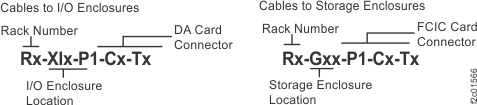
    Figure 2. Point-to-point cabling diagram for storage enclosure FC-AL and Flash PCIe cables (Models 981, 98E, single-phase power, rear view, racks 1, 2)
    Point-to-point cabling diagram for storage enclosure PCIe and FC-AL cables (Models 981, 98E, rear view, racks 1, 2)
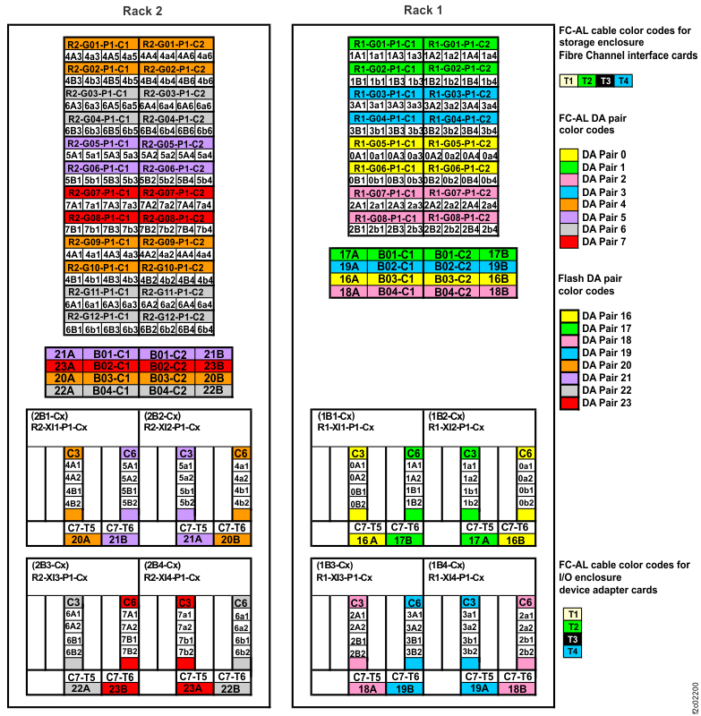
    Figure 3. Point-to-point cabling diagram for the FC-AL cables (Models 981, 98E, single-phase power, rear view, racks 3, 4, 5)
    Point-to-point cabling diagram for the FC-AL cables (Models 981, 98E, rear view, racks 3, 4, 5)
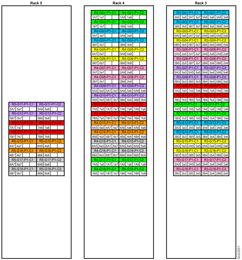
    Figure 4. Point-to-point cabling diagram for storage enclosure PCIe and FC-AL cables (three-phase Models 981, 98E, rear view, racks 1, 2)
    Point-to-point cabling diagram for storage enclosure PCIe and FC-AL cables (three-phase Models 981, 98E, rear view, racks 1, 2)
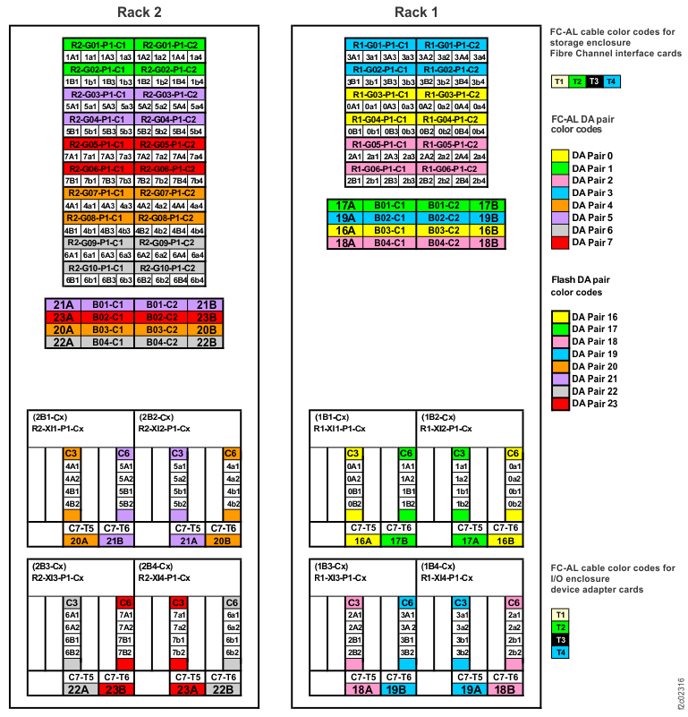
    Figure 5. Point-to-point cabling diagram for the FC-AL cables (three-phase Models 981, 98E, rear view, racks 3, 4, 5)
    Point-to-point cabling diagram for the FC-AL cables (three-phase Models 981, 98E, rear view, racks 3, 4, 5)
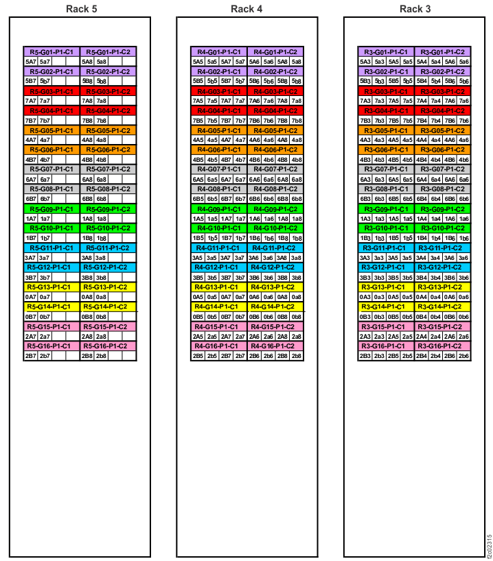
  3. Route the FC-AL cables to the destination rack.
    1. Do not connect the FC-AL cables to the storage enclosure Fibre Channel interface cards until directed later in this procedure.
    2. Route each cable bundle  1  to the destination rack through the rack to rack holes at the upper rear of each rack. See Figure 6 and Figure 7.
      Figure 6. Routing remote power control cables and optical cables between racks
      Note: Models 980 and 98B shown, routing for other models is similar
      Routing remote power control cables and FC-AL cables between racks
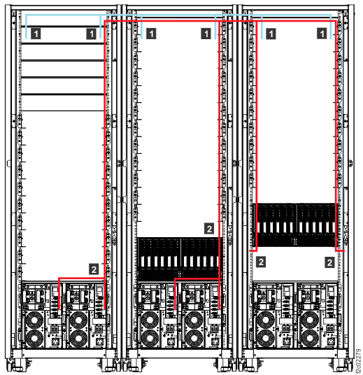
      Figure 7. Routing rack to rack power control and FCAL cables across a rack (earlier model shown, routing for Models 98x similar)
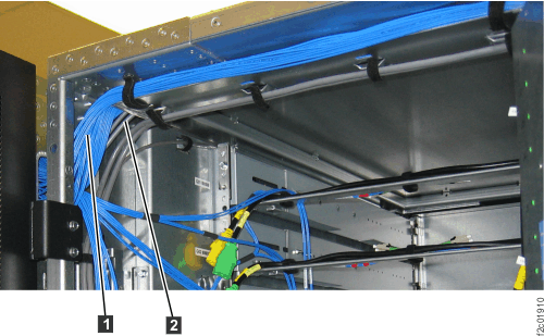
  4. Route the FC-AL cables to the destination storage enclosure.
    1. Do not connect the FC-AL cables to the storage enclosure Fibre Channel interface cards until directed later in this procedure.
    2. FC-AL cables that will connect to the Fibre Channel interface card in the left side of a storage enclosure are routed down the left side of the rack.
      • Left-side cables have "C1" in the location code (for example, Rx-XIx-P1-C1-Tx), or the last character in the connection designator will be odd (for example, 2A5).
    3. FC-AL cables that will connect to the right Fibre Channel interface card in a storage enclosure are routed down the right side of the rack.
      • Right-side cables have "C2" in the location code (for example, Rx-XIx-P1-C1-Tx), or the last character in the connection designator will be even (for example, 2A6).
  5. Do not remove the black rubber protective connector covers at the end of each cable. Do not connect the cables until directed later in the installation.
  6. Find the expansion rack that you are installing in the first column of the following table and then use the Go to: column to continue the installation.
    Expansion rack position Go to:
    Rack-3 Installing and testing the Rack-3 storage enclosures
    Rack-4 Installing and testing the Rack-4 storage enclosures
    Rack-5 Installing and testing the Rack-5 storage enclosures