MAP2010 RPC card causes false fence
The failing RPC card has an internal problem that is causing it to fence the working RPC card when it should not.
About this task
MAP2010 Section-1
Procedure
-
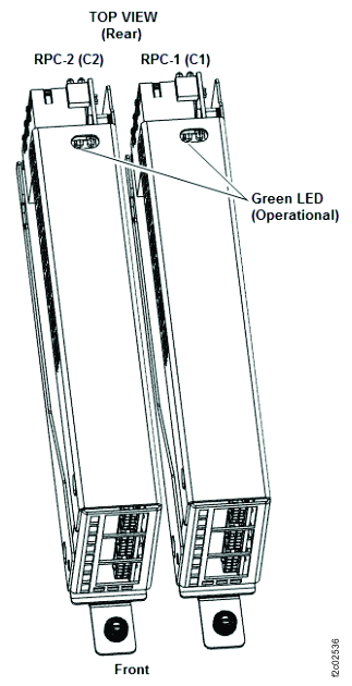
Verify that one of the two cards is fenced. Observe the green
operational
LED on each RPC card. See Figure 1. Is the green LED indicator off on one of the
cards?
on each RPC card. See Figure 1. Is the green LED indicator off on one of the
cards?
- Yes, continue at the next step.
- No, neither RPC is fenced. The original failing condition is no longer present. Contact your next level of support before you cancel this problem.
- Return to the SAEL problem screen and continue. Note: Both RPC cards are not available and normal guided FRU replace procedures are used.
Figure 1. LEDs on the RPC cards Note: Model 961 shown. Models 98x similar.
MAP2010 Section-2
Procedure
-
Place the management enclosure (Figure 2) in the service
position and remove the top cover to gain access to the RPC card LED indicators.
- At the front of the rack, loosen the two screws and slide the Management enclosure out to the service position.
- At the rear of the cover, loosen the two thumbscrews and slide the cover back until it can be lifted and off.
Figure 2. Management enclosure (front view) 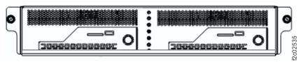
-
Verify that one of the two RPC cards is fenced (green LED indicator is not lit). Observe the
green LED indicator on each RPC card. (Figure 3).
Is the green LED indicator not lit on one of the RPC cards?
- Yes, an RPC card is fenced, continue at the next step.
- No, neither RPC is fenced. The original failing condition is no longer present. Contact your next level of support before you cancel this problem.
Figure 3. RPC card operational green LED