MAP2050 Loss of AC Input to a single primary power supply
The primary power supply (PPS)
is reporting a loss of line cord AC input. This loss can be due to a loss of customer line cord
power or an internal failure in the AC to DC conversion section of the PPS.
About this task
This MAP assumes that only one PPS in this storage facility reported a loss of line cord AC input. If
more than one PPS in this storage facility lost AC input, a different serviceable
event would be created to report customer power problems that did not require a repair
action.
MAP2050 Section-1
About this task
Note: If you replace the PPS FRU and the failure
still occurs, replace the optional modules in the PPS also. For Model 94x, the
optional modules, if present, are in the Ex-E2 and/or Ex-E3 locations.
For Model 95x, the optional module, if present, is in the Ex-E2 location.
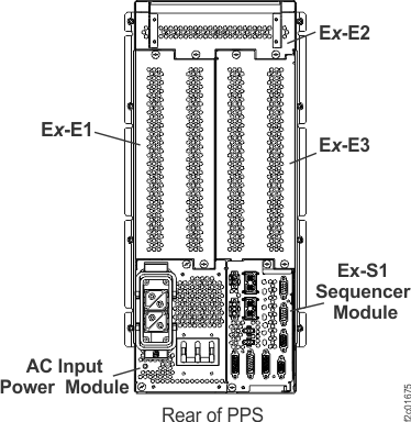
Figure 1. Location codes for the PPS (rear
view)
Procedure
Using the location for the PPS FRU in
the problem record, locate the PPS that
reported the loss of line cord AC.
Observe the AC INPUT GOOD LED that is on the front of the PPS.
No, have the customer determine why the circuit breaker was off. When it is safe, have the
customer set the circuit breaker to On and ensure that the PPS powers up properly. Then, go to step 9.
Ensure that all of the power connections
between the customer power source and the PPS that
is reporting the failure are properly connected before you continue
with the next step.
At the rear of the rack, switch the failing PPS input
circuit breaker to off (down).
At the rear of the rack, disconnect the mainline power
cable from the failing PPS.
Yes, the PPS is failing. Return to
the repair procedure to complete the replacement of the PPS. The line cord is reconnected as part of
the FRU replacement.
Click Close in the current service information window.
One or more HMC repair screens might prompt you for the result of using the service procedure in
the MAP. Select Problem not fixed.
Select No when prompted for whether you exchanged any parts.
Select Yes when prompted for whether you isolated the problem.
Select the PPS from the FRU list. The HMC begins the FRU exchange process for the selected
FRU.
No, ensure that the line cord is correctly connected to the customer power system.
Report the problem to the customer, and after they restore proper power that you can verify by
measuring once again, complete the repair procedure for the PPS. These steps reset any PPS fence that occurred. Then, go to step 9 to ensure the PPS is available.
The functional code might have fenced (removed from active use) the PPS as part of the error recovery. Determine
whether the PPS is fenced.
Start the View Storage Facility State task:
In the Service
interface, click Storage Facility Management > storage facility:
From the navigation area, click Storage Facility Management > storage facility.
From the bottom Task area, click Service Utilities > View Storage Facility State.
In the DS8000 storage management GUI system area, click Service > Storage System > View Storage Facility State.
A window displays the status (passed/failed) of 25 or more system checks.
At the bottom of the System Check Type column, observe the status of the Fenced
Resources.
Find the status that is displayed:
PASSED (no resources are fenced), close the serviceable event and exit this MAP.
No, the PPS is not fenced. Close
the serviceable event and exit this MAP. There should be
serviceable events for resources that are fenced. These fenced resources need to be
repaired.
The PPS fence needs to be reset by
using the PPS FRU replace procedure. Return to the repair screen you followed to this point and do a
pseudo repair of the FRU. A pseudo repair of the PPS means that you use the normal FRU
replacement procedures, but you do not replace the PPS. In this situation (SRC BE19100x, directing
MAP2050), it is not necessary to disconnect and reconnect PPS cables as part of the pseudo
repair.
Read all these substeps before you go to substep b, which closes this information center
window. To view this MAP in a separate information center window, click Help
in the upper right corner of the main HMC GUI screen and navigate to the MAP.
Click Close in the current service information window.
One or more HMC repair screens might prompt you for the result of using the service procedure
in the MAP. Select Problem not fixed.
Select No when prompted for whether you exchanged any parts.
Select Yes when prompted for whether you isolated the problem.
Select the PPS from the FRU list. The HMC begins the FRU exchange process for the selected
FRU.