MAP20F6 Expansion rack DC-UPS to rack 1 RPC communication problem detected
A DC-UPS to RPC card communication problem was detected. The problem normally will be mis-plugged DC-UPS or RPC card cables detected during an install or repair action. Mis-plug in this case means cross connected between the RPC cards or between the DC-UPSs.
About this task
MAP20F6 Section-1
Procedure
- Use the tables below to physically trace each cable and
ensure all three ends are correctly plugged. If a problem is found,
you must not hot plug the cables to correct the problem. Instead,
return and repeat the procedure during which the cables were connected.
If this is not possible, contact your next level of support.
Note: If the cables are crossed, it is not possible to do a psuedo repair of one RPC card or DS-UPS to correct the problem. Next level of support may need remote access to correct this.
Table 1. RPC-1 card to DC-UPS-1 and DC-UPS-2 RPC-1 card connector
(see Figure 1 or Figure 2)DC-UPS in Rack number DC-UPS-1 (left or upper) connector
(see Figure 3 or Figure 4)DC-UPS-2 (right or lower) connector
(see Figure 3 or Figure 4)C1-J201 1 J6 J6 C1-J203 2 J6 J6 C1-J205 3 J6 J6 C1-J207 4 J6 J6 C1-J209 5 J6 J6 Table 2. RPC-2 card to DC-UPS-1 and DC-UPS-2 RPC-2 card connector
(see Figure 1 or Figure 2)DC-UPS in Rack number DC-UPS-1 (left or upper) connector
(see Figure 3 or Figure 4)DC-UPS-2 (right or lower) connector
(see Figure 3 or Figure 4)C2-J201 1 J7 J7 C2-J203 2 J7 J7 C2-J205 3 J7 J7 C2-J207 4 J7 J7 C2-J209 5 J7 J7 Figure 1. Location codes for the RPC card (Model 98x) 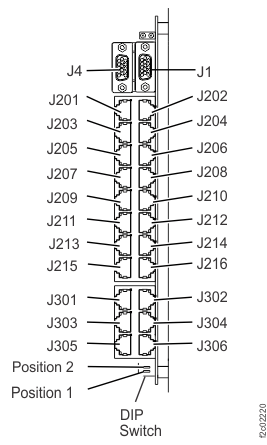
Figure 2. Location codes for the RPC cards (Model 961) 
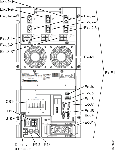
Figure 3. Location codes for the DC-UPS (Models 98x, single-phase) (rear) 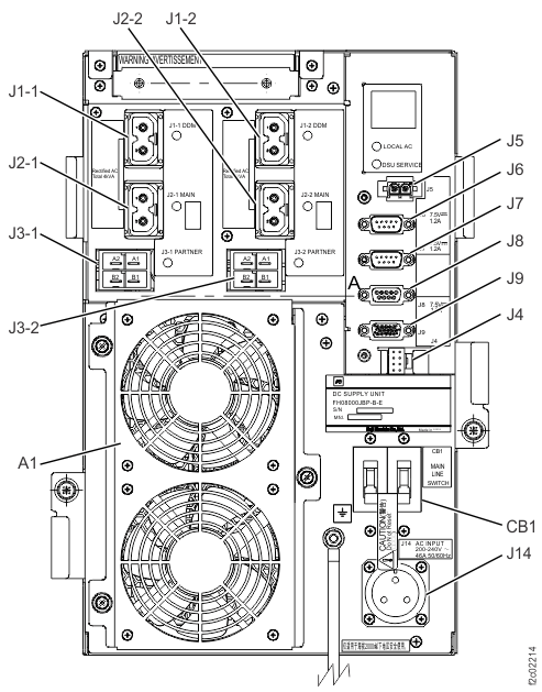
Figure 4. Location codes for the DC-UPS (Models 961, 96E, and Models 98x, three-phase) (rear)