MAP2221 CEC enclosure to RPC card RS-485 serial path failure
One or more serial interfaces between the CEC enclosure RS-485 serial interface card and RPC cards is failing.
MAP2221 Section-1
Procedure
-
There are four RS-485 serial cables between the CEC enclosures and RPC
cards. Each is a separate communication path.
- Model 96x. See Figure 1.
- Models 980, 981, 984, 985, and 986. See Figure 2.
- Models 982, and 988. See Figure 3.
- Model 983. See Figure 4.
Figure 1. Serial cables, CEC enclosure RS-485 card to RPC cards, model 961 
Figure 2. Serial cables, CEC enclosure RS-485 card to RPC cards, models 980, 981, 984, 985, and 986 
Figure 3. Serial cables, CEC enclosure RS-485 card to RPC cards, models 982 and 988 
Figure 4. Serial cables, CEC enclosure RS-485 card to RPC cards, model 983 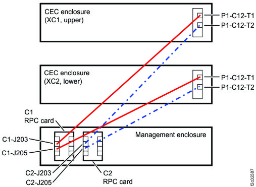
MAP2221 Section-2 (One CEC enclosure RS-485 serial interface failed to both RPC cards)
Procedure
-
Ensure that both serial interface cables are properly connected to the
CEC enclosure RS-485 serial interface card connectors:
- Model 96x. See Figure 5. P1-C5-T1 is upper cable with gray label, and P1-C5-T2 is lower cable with yellow label.
- Models 980, 983,and 984. See Figure 6. P1-C12-T1 is upper cable with gray label, and P1-C12-T2 is lower cable with yellow label.
- Models 981, 985, and 986. See Figure 7. P1-C12-T1 is upper cable with gray label, and P1-C12-T2 is lower cable with yellow label.
- Models 982 and 988. See Figure 8. P1-C7-T1 is upper cable with gray label, and P1-C7-T2 is lower cable with yellow label.
Figure 5. Location codes for the CEC enclosure (rear view) (Model 961) 
Figure 6. Location codes for CEC enclosure (rear view) (Models 980, 983, 984) 
Figure 7. Location codes for the CEC enclosure (rear view) (Model 981, 985, 986) 
Figure 8. CEC enclosure location codes (rear view) (Models 982, 988) 
- The location code of the CEC enclosure RS-485 serial interface card appears in the serviceable event FRU list that sent you here.
- If a cable is unplugged, or if cables are crossed, do a pseudo-repair of the CEC enclosure RS-485 serial interface card and instead of replacing the card, properly connect the cable or cables. For details, see MAP1235 Section-4, Exit Procedure 4: Problem not isolated, continue FRU list. Select the RS-485 serial interface card from the FRU list.
-
Ensure that the RS-485 serial interface cables are properly connected to both RPC cards.
- Model 961, 98x (not 983). See Figure 9.
- CEC enclosure 1 (upper) to both RPC cards J212 connector
- CEC enclosure 2 (lower) to both RPC cards J216 connector
- Model 983. See Figure 10.
- CEC enclosure 1 (upper) to both RPC cards J203 connector
- CEC enclosure 2 (lower) to both RPC cards J205 connector
- Is a cable disconnected?
- Yes, do a pseudo-repair of the CEC enclosure RS-485 serial interface card and instead of replacing the card, properly connect the cable. For details, see MAP1235 Section-4, Exit Procedure 4: Problem not isolated, continue FRU list. Select the RS-485 serial interface card from the FRU list.
- No, go to the next step.
Figure 9. Location codes for the RPC card (Model 98x, not 983) 
Figure 10. Location codes for the RPC card (Model 983), rear of management enclosure 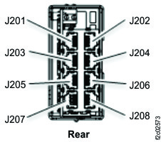
- Model 961, 98x (not 983). See Figure 9.
MAP2221 Section-3 (Both CEC enclosure RS-485 serial interfaces failed to one RPC card)
About this task
Note: The RPC card is fenced. The following procedure resets the fence by either replacing the card
or doing a pseudo-repair of the card.
Procedure
-
Observe the RPC card operation LED indicator. (Model 96x, 98x)
-
Is the green LED indicator
 lit solid? See Figure 11.
Figure 11. LEDs on the RPC card (Model 98x, not 983) 
-
Is the green LED indicator
-
At the front of the rack, slide the management enclosure out to the service position and remove
the top cover.
Note: The management enclosure is below the two CEC enclosures.
- Fully loosen the left and right captive thumb screws.
- Slide the management out fully so the sliding rails lock into place.
- At the rear of the top cover, fully loosen the left and right captive thumb screws.
- Slide the cover back until it lifts off.
Figure 12. Management enclosure (front) 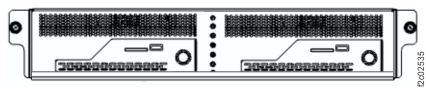
-
Observe the RPC card LED indicators.
-
At the top rear of the RPC card, is the green operation LED indicator lit solid? See Figure 13.
Figure 13. LEDs on RPC card (Model 983) 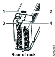
Figure 14. Location codes for the RPC (Model 983), front view 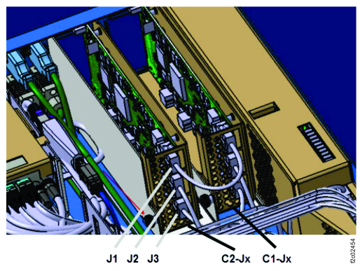
-
At the top rear of the RPC card, is the green operation LED indicator
MAP2221 Section-4 (One CEC enclosure RS-485 serial interface failed to one RPC card)
About this task
Note: The RPC card is fenced. The following procedure resets the fence by either replacing the card
or doing a pseudo-repair of the card.