MAP2800 Management enclosure power supply reports a power fault
MAP2800 Section-1
About this task
SRCs in serviceable event:
- BE198D61 Management enclosure 12 V power distribution cable at power supply (E31) J3 not detected.
- BE198D83 Management enclosure 12 V power distribution cable at power supply (E32) J3 not detected.
- BE198D94 A power fault for the RPC card (C1) is being reported by both management enclosure power supplies.
- BE198D95 A power fault for the RPC card (C2) is being reported by both management enclosure power supplies.
- BE198D96 A power fault for the primary management console (MC1) is being reported by both management enclosure power supplies.
- BE198D97 A power fault for the secondary management console (MC2) is being reported by both management enclosure power supplies.
- BE198D98 A power fault for Ethernet switch SW1 (Black network) is being reported by both management enclosure power supplies.
- BE198D99 A power fault for Ethernet switch SW2 (Gray network) is being reported by both management enclosure power supplies.
Procedure
-
At the front of the rack, slide the management enclosure out to the service position and remove
the top cover. See Figure 1.
Note: The management enclosure is below the two CEC enclosures.
- Fully loosen the left and right captive thumb screws.
- Slide the management out fully so the sliding rails lock into place.
- At the rear of the top cover, fully loosen the left and right captive thumb screws.
- Slide the cover back until it lifts off.
Figure 1. Management enclosure (front) 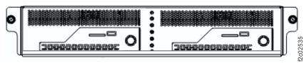
-
Inspect the management enclosure 12 V power distribution cable that connects to each
management enclosure power supply J3 connector.
The cable connects to both power supplies, both Ethernet switches, both fan assemblies and both management consoles. See Figure 2 and Figure 3.
Is the cable unplugged?
- Yes. Exit the MAP, select the next FRU in the list (management enclosure power supply) and
do a pseudo-repair.
When directed, disconnect the cables. Do not remove the power supply. When directed, connect the cables including the J3 cable. Complete the repair normally. - No. Exit the MAP, select the next FRU in the FRU list.
Figure 2. Management enclosure 12V power distribution cable, eight connectors 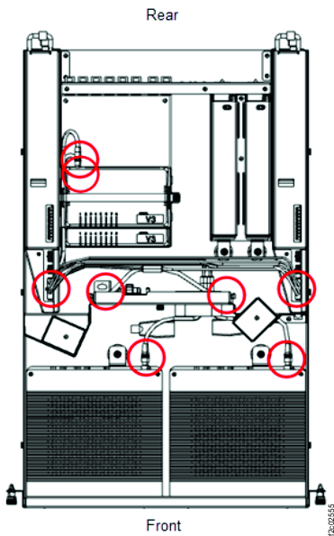
Figure 3. Management enclosure 12V power distribution cable 
- Yes. Exit the MAP, select the next FRU in the list (management enclosure power supply) and
do a pseudo-repair.