MAP2870 UPS visual symptoms

MAP2870 isolates visual symptoms of the UPS control panel and the input circuit breaker.

MAP2870 Section-1

Procedure

  1. At the front of the rack, locate the UPS to be repaired. See Figure 1.
    Figure 1. Locations of management module enclosures
    Storage controller module (enclosures shown)
  2. Select the following that applies:
    • You were sent to this MAP from another MAP. Go to step 4.
    • You were sent to this MAP from a serviceable event FRU list. Go to step 3.
  3. Is there a related open serviceable event?
    • Yes, exit this MAP and the related serviceable event to continue the repair.
    • No, go to step 4.
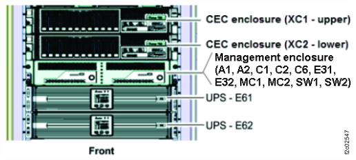
  4. At the front of the rack, observe the UPS control panel. See Figure 2.
    Is the AC icon Callout label 1 lit? See Figure 3.
    Figure 2. UPS control panel
    UPS control panel
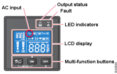
    Figure 3. UPS control panel with indexes
    UPS control panel with indexes
  5. Observe the UPS control panel Fault LED (red). See Figure 2.
    Select the condition that applies:
  6. Is the Output status LED (green) lit solid? See Figure 2.
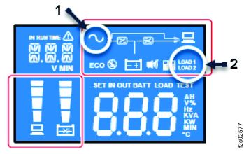
  7. Are the LOAD 1 and LOAD 2 icons Callout label 5 lit? See Figure 3.

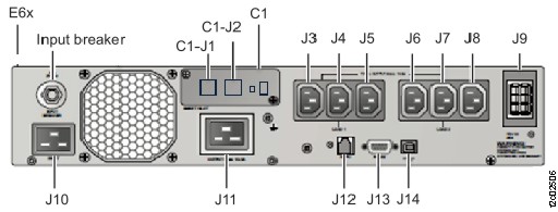
MAP2870 Section-3 Fault LED on

Procedure

  1. When the Fault LED is on, an error code is displayed.

    The following error codes can be displayed. These are provided for general information only. The UPS is not repairable.

    Table 1.
    Error code Meaning
    E11 Charger fault
    E12 Fan fault
    E13 Over temperature
    E14 +/- DC bus high / low
    E16 Inverter fault
    E18 DC-DC fault
    E19 Abnormal output/inverter voltage
    E21 O/P short
    sd0 Emergency shutdown
    sd1 Remote shutdown
    sd2 Shutdown After shutdown enabled
    sd3 Battery Save shutdown
    sd4 Battery low shutdown
  2. Replace the UPS. Exit this MAP.

MAP2870 Section-4 Fault LED flashing

Procedure

  1. There are two faults that can cause the Fault LED to flash:
    1. Battery related fault. See Figure 5. Go to step 2.
    2. UPS overcurrent fault. See Figure 6. Go to step 3.
      Figure 5. UPS control panel battery icon
      UPS control panel battery icon
      Figure 6. UPS control panel overload icon
      UPS control panel overload icon
  2. Battery related fault. Four conditions can cause this fault:
    • Battery is not physically installed. Physically install and connect the battery.
    • Battery cable is not connected and needs to be connected.
    • Battery is failing and needs to be replaced.
    • UPS is failing and needs to be replaced.
    1. If there is a related open serviceable event, use that to correct the battery problem.
    2. If there is not a related open serviceable event, use MAP1230 Replace a FRU without using a serviceable event.
  3. UPS overcurrent fault.
    1. If there is a related open serviceable event, use that to correct the battery problem.
    2. If there is not a related open serviceable event, exit this MAP and go to MAP2890 UPS overcurrent (Model 983).

MAP2870 Section-5 Output status LED off

Procedure

The AC input icon is on. The Output status LED is off.
  1. The UPS is in standby mode.
  2. The J3-J8 output connectors do not have power.
  3. Exit this MAP and do a pseudo repair of the PPS. When directed to replace the UPS, reuse the existing PPS. If the same failure occurs, replace the UPS with a new UPS.

MAP2870 Section-6 LOAD1, LOAD2 icon off

Procedure

  1. The AC input icon is on and the Output status LED is on.
    Select the following condition that applies.
    • Both the LOAD1 and LOAD2 icons are not lit. Go to step 2.
    • Only one icon (LOAD1 or LOAD2) is lit. Go to step 3.
  2. The LOAD1 and LOAD2 icons are not lit.
    Note: This is the expected state of the LOAD1 and LOAD2 icons when the UPS was powered off by the UPS control panel OFF button (see Figure 2), and then input power to the UPS was lost. When the input power is restored, the UPS returns to the state it was in before loss of power.
    1. Press the UPS control panel ON button for three seconds and release it after you hear one beep.
    2. Are the UPS LOAD1 and LOAD2 icons both lit?
        • Yes. The UPS is now in a normal state. Exit this MAP and check for open related serviceable events.
        • No. Exit this MAP and replace the failing UPS.
  3. Only one icon (LOAD1 or LOAD2) is lit. Power off and then power on the UPS.
    1. Press the UPS control panel OFF button for three seconds and release it after one beep.
    2. Press the UPS control panel ON button for three seconds and release it after one beep.

    Are the UPS LOAD1 and LOAD2 icons both lit?

    • Yes. The UPS is now in a normal state. Exit this MAP and check for open related serviceable events.
    • No. Exit this MAP and replace the failing UPS.