Powering on the racks
Before you begin
Procedure
-
At the rear of the rack, connect the mainline power cables to input connector J10 of both UPSs.
See Figure 1.
- At the rear of UPS loosen, but do not remove, the cable retention bracket screw
 and lift up to remove the bracket
  . See
Figure 2.
. See
Figure 2. - Connect the mainline power cables.
- Reinstall the cable retention brackets.
- At the rear of UPS loosen, but do not remove, the cable retention bracket screw
- Connect the mainline power cables to source power. If circuit breakers are used, switch
the circuit breakers on.
- Record the time the mainline power cables were connected _______________________.
- Wait 1 minute for the UPSs to stabilize and then continue to the next step.
Figure 1. Location codes for the UPS (Model 983), rear view 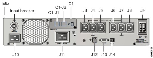
Figure 2. UPS input power cable retention bracket (rear) 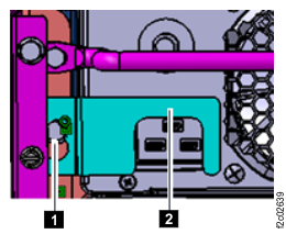
-
At the front of the rack, observe the LED indicators and LCD icons on the control panel of both
UPSs. Use Table 1 to find the
condition that applies.
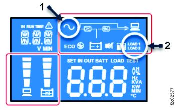
Table 1. UPS LED indicators and LCD icons with power connected AC (input)
1 Figure 4Fault LED
Figure 3Output status LED
Figure 3Action ON (solid) OFF ON Normal condition, continue with the next step. OFF or flashing (any) (any) If no LEDs are on, ensure power is available. Otherwise, go to MAP2870 UPS visual symptoms (any) ON or flashing (any) (any) (any) OFF Figure 3. UPS control panel 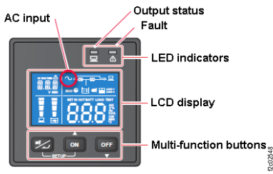
Figure 4. UPS control panel with indexes