Exchange the DC-UPS battery service module (BSM) set
Before you begin


 Use approved ESD procedures to prevent damage.
Attention:
- This procedure is not a stand-alone procedure. Customer disruption and damage to the hardware might occur when microcode and power boundaries are not in the proper conditions for this service action.
- If a serviceable event FRU repair directed you to this procedure, the microcode and power boundaries are already set.
- If a serviceable event FRU repair did not direct you to this procedure, see MAP1230 Replace a FRU without using a serviceable event.
Notes:
- All the cables and FRUs to be removed must be uniquely identified so they can be reinstalled correctly.
- The battery service module (BSM) set contains four battery modules.
- The upper right BSM (Ex-E12-E1) is the primary and contains status LEDs. It can be physically installed only in the upper right position.
- The other three BSMs (Ex-E12-E2, E3 and E4) are secondary BSMs. They can be physically installed only in those positions.
- Each BSM (primary and secondary) has EEPROMs that store the "Born on date" and the service history.
- All four BSMs in a set must be replaced at the same time, and must not be intermixed with a different BSM set.
- Each BSM in the set share a common serial number on the Born On Date label.
- You are using this procedure to exchange a BSM set. Unless directed by a MAP or next level of support, you must replace the FRU with a new FRU. Completing a "pseudo-repair" with an out-of-date or defective FRU, or closing a serviceable event without exchanging the FRU, can result in a customer event.
- If an installed earthquake resistance kit prevents you from accessing this FRU, refer to MAP1600.
Remove the BSM set
Procedure
- To locate this FRU, take one of the following actions and then return here and
continue to replace the FRU:
- If this FRU has a FRU identify indicator, use the FRU identify indicator,
which is listed in MAP1240 Locating FRUs by using identify indicators.
If not, use the location
code.Note: There might be cases where the FRU failure or fencing conditions prevent the FRU LED indicator from being lit even if the FRU has power.
- Use the location code, which is listed in MAP1245 Finding FRUs by using location codes.
- If there is no FRU identify indicator or location code, you were sent here by an isolation MAP or symbolic FRU procedure. Use the information in that procedure and the figures in this procedure to locate the proper part to exchange.
Figure 1. Battery service module (BSM) set locations (Models 98x single-phase power) (front) 
Figure 2. Battery service module (BSM) set locations (Models 98x three-phase power) (front) 
- If this FRU has a FRU identify indicator, use the FRU identify indicator,
which is listed in MAP1240 Locating FRUs by using identify indicators.
If not, use the location
code.
-
Remove the BSM set cover (if present) from the BSM set enclosure. Loosen the screws
 at both
sides to remove. See Figure 3.
at both
sides to remove. See Figure 3.
Figure 3. BSM set enclosure cover (Models 98x and 8xE, single-phase power) (front) 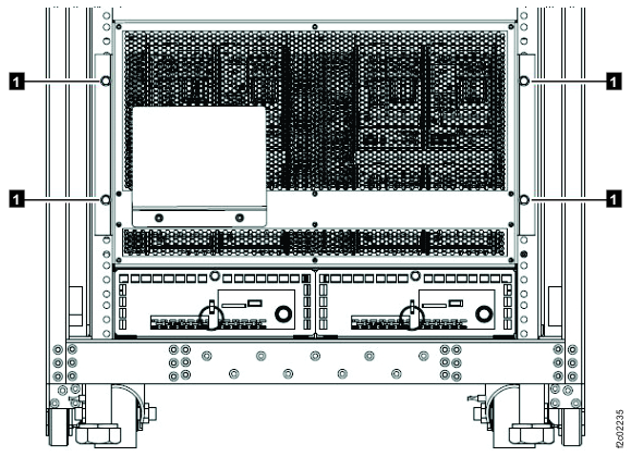 Note: BSM set enclosure cover for single-phase power configuration shown, enclosure cover for three-phase power is similar.
 -
Are any of the following cables either unplugged or missing? See Figure 4 or Figure 5.
 and
and  BSM set signal cable. Note:
is
permanently attached on later BSM set versions.
BSM set signal cable. Note:
is
permanently attached on later BSM set versions. and
and  BSM set 208V power cable
- Yes, do not replace the BSM set. Instead, go to the next step, and when you are directed to replace the BSM set, connect the disconnected cable(s).
- No, go to the next step.
Figure 4. Battery service module (BSM) set for Models 98x, single-phase power, (front) 
Figure 5. Battery service module (BSM) set (Models 98x, three-phase power) (front) 
-
Remove the retaining screw or
 (Figure 4 or
Figure 5) at the top of each
battery service module that is being replaced.
(Figure 4 or
Figure 5) at the top of each
battery service module that is being replaced.
- Disconnect the BSM signal cable from the three secondary
BSM module J31 connectors. (Figure 6)
Figure 6. Battery service module, secondary, locations (front) 
- Leave the BSM signal and power cables connected to the
primary BSM module J30 and J20 connectors. (Figure 7)
Figure 7. Battery service module, primary, locations (front)