Exchange the I/O enclosure PCIe storage interface card

Before you begin

Icon for electrostatic discharge wrist strapUse approved ESD procedures to prevent damage.

Attention:
  • This procedure is not a stand-alone procedure. Customer disruption and damage to the hardware might occur when microcode and power boundaries are not in the proper conditions for this service action.
  • If a serviceable event FRU repair directed you to this procedure, the microcode and power boundaries are already set.
  • If a serviceable event FRU repair did not direct you to this procedure, see MAP1230 Replace a FRU without using a serviceable event.
Notes:
  • All the cables and FRUs to be removed must be uniquely identified so they can be reinstalled correctly.
  • If an installed earthquake resistance kit prevents you from accessing this FRU, refer to MAP1600.

Remove the I/O enclosure PCIe storage interface card

Procedure

  1. To locate this FRU, take one of the following actions and then return here and continue to replace the FRU:
    • If this FRU has a FRU identify indicator, use the FRU identify indicator, which is listed in MAP1240 Locating FRUs by using identify indicators. If not, use the location code.
      Note: There might be cases where the FRU failure or fencing conditions prevent the FRU LED indicator from being lit even if the FRU has power.
    • Use the location code, which is listed in MAP1245 Finding FRUs by using location codes.
    • If there is no FRU identify indicator or location code, you were sent here by an isolation MAP or symbolic FRU procedure. Use the information in that procedure and the figures in this procedure to locate the proper part to exchange.
  2. Most, but not all, FRUs have identify indicators. Use the flashing amber or solid blue FRU identify indicators to ensure that you are working on the correct enclosure or FRU.
  3. This FRU contains the PCIe storage interface card and PCIe cable that connects it to a storage enclosure RAID controller card.
    The PCIe storage interface card only has redrive circuits for the PCIe interface. The code cannot isolate an interface error to the card or the cable, so they are replaced together. The only exception is if a visual symptom such as an unplugged cable is found.
  4. Inspect both ends of the PCIe cable for proper connection. Use the following figures to determine the location of both ends of the PCIe cable that is suspect.
    Figure 1. PCIe cable connections (standard configuration, Rack-1, rear) (Models 961/96E)
    PCIe cable connections (standard configuration, Rack-1, rear) (Models 961/96E)
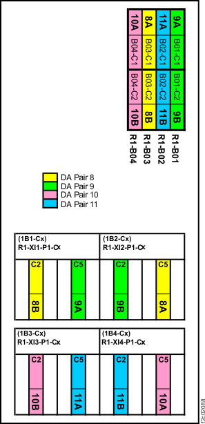
    Figure 2. PCIe cable connections (standard configuration, Rack-2, rear) (Models 961/96E)
    PCIe cable connections (standard configuration, Rack-2, rear) (Models 961/96E)
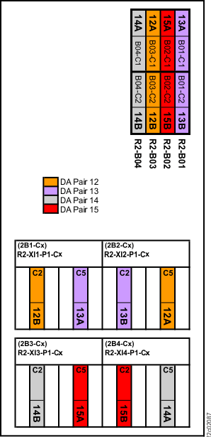
    Figure 3. PCIe cable connections (DS8870 all-flash, Rack-1, rear) (Model 961)
    PCIe cable connections (DS8870 all-flash, Rack-1, rear) (Model 961)
  5. Is the PCIe cable properly connected at both ends?
    • Yes, go to the next step to replace the PCIe cable and PCIe storage interface card.
    • No, the PCIE cable is disconnected. There is no need to replace the PCIe cable and PCIe storage interface card. Instead, when directed to replace the FRU, you will reconnect the cable and continue the repair.
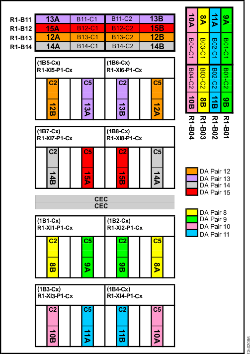
  6. At the rear of the rack, remove the PCIe storage interface card. See Figure 4.
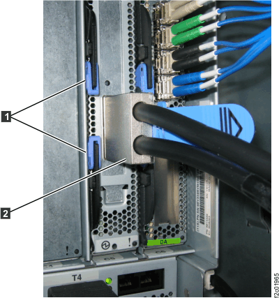
    1. Disconnect the PCIe cable Callout label 2.
    2. Unlatch the two blue levers Callout label 1 to the left of the card being removed. See Figure 4.
    3. Slide the card out.
    Figure 4. I/O enclosure RAID controller card
    I/O enclosure RAID controller card
  7. Remove the cable from the rack.
    1. Trace the cable from the PCIe storage interface card to the storage enclcosure RAID controller card.
    2. DO NOT DISCONNECT the cable until you know it is the other end of the cable that is already disconnected.
    3. Remove the cable ties, begin removing the cable and disconnect it.

Install the I/O enclosure PCIe storage interface card

Procedure

  1. Install the new PCIe storage interface card. See Figure 4.
    1. Ensure the blue levers Callout label 1 are open on the new card.
    2. Slide the card in and the latch the two blue levers Callout label 1.
    3. Connect the PCIe cable Callout label 2. Gently push and pull to ensure it is seated.
  2. Install the new PCIe cable.
    1. Route the cable neatly and use the cable ties to secure it.
    2. Connect both ends.
  3. Exit this service information center parts exchange procedure and return to the procedure that sent you here.