Exchange the local remote switch card

Before you begin

Icon for electrostatic discharge wrist strapUse approved ESD procedures to prevent damage.

Attention:
  • This procedure is not a stand-alone procedure. Customer disruption and damage to the hardware might occur when microcode and power boundaries are not in the proper conditions for this service action.
  • If a serviceable event FRU repair directed you to this procedure, the microcode and power boundaries are already set.
  • If a serviceable event FRU repair did not direct you to this procedure, see MAP1230 Replace a FRU without using a serviceable event.
Notes:
  • All the cables and FRUs to be removed must be uniquely identified so they can be reinstalled correctly.
  • If an installed earthquake resistance kit prevents you from accessing this FRU, refer to MAP1600.

About this task

Remove the local remote switch card

About this task

Procedure

  1. To locate this FRU, take one of the following actions and then return here and continue to replace the FRU:
    • If this FRU has a FRU identify indicator, use the FRU identify indicator, which is listed in MAP1240 Locating FRUs by using identify indicators. If not, use the location code.
      Note: There might be cases where the FRU failure or fencing conditions prevent the FRU LED indicator from being lit even if the FRU has power.
    • Use the location code, which is listed in MAP1245 Finding FRUs by using location codes.
    • If there is no FRU identify indicator or location code, you were sent here by an isolation MAP or symbolic FRU procedure. Use the information in that procedure and the figures in this procedure to locate the proper part to exchange.
  2. Most, but not all, FRUs have identify indicators. Use the flashing amber or solid blue FRU identify indicators to ensure that you are working on the correct enclosure or FRU.
  3. At the right rear of the rack, put the Local/Remote switch to the Local position (left - toward the front of the rack). See Figure 1.
    Attention: The switch must be placed in the Local position for this repair.
    Figure 1. Location codes for the local remote switch card
    Location codes for the local remote switch card
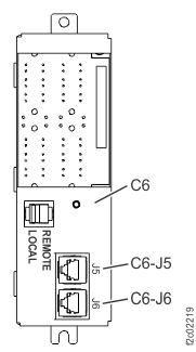
    Table 1. RPC to local remote switch card cables
    From RPC port RPC card (facing rear) To local remote switch card connector
    C1-J204 Left C6-J5
    C2-J204 Right C6-J6
  4. Disconnect the RPC cables from the switch card connectors J5 and J6.
  5. Loosen and remove the fastener that secures the card assembly to the rack.
  6. Slide the card up and then remove it.

Replace the local remote switch card

Procedure

  1. Ensure the Local/Remote switch on the card being installed is in the Local position (left).
  2. Gently slide the card assembly into the tabs on the rack wall. Replace and tighten the fastener.
  3. Connect the RPC cables to the switch card connectors J5 and J6. Ensure that the cables are not cross-connected.
  4. The FRU verification tests for this FRU cannot detect disconnected or cross-connected cables. Use the location code label on each cable to ensure that it is properly connected.
  5. Observe the local/remote switch card amber identify LED.

    Is the LED blinking?

    • Yes, go to step 6.
    • No. The signal to blink the ID LED comes from both RPC cards. Ensure you properly connected the cables in step 4. If they are properly connected, call the next level of support or replace the local/remote switch card again.
  6. Put the Local/Remote switch to the Remote position (right - toward the rear of the rack).
  7. Exit this service information center parts exchange procedure and return to the procedure that sent you here.