Completing the logical installation of the I/O enclosures
The steps in this procedure power-on and logically install each I/O enclosure pair. The lower pair will be logically installed first followed by the upper pair (if present).
Procedure
-
View the storage facility status. If any of the system check results
display as FAILED, view the details and refer to
MAP1100 View storage facility state (end of call). Before you continue the installation, all status fields should
display as PASSED.
- To display further details, select a row and click Details.
A window displays the status (passed/failed) of 25 or more system checks. The following is an example.Figure 1. Window: View Storage Facility State 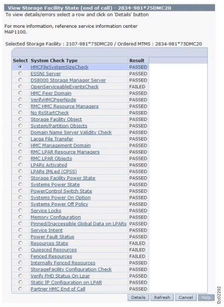 Note: If the status for Large File Transfer displays as FAILED, the remaining System Check Types below it cannot be displayed.
 -
Select the condition that applies and corresponding action to take. Refer to Table 1, Figure 2, Figure 3, Figure 4, Figure 5, and
Figure 6.
Table 1. Rack-2 contents and actions Rack-2 contains these items Action to take 1 or more high-performance flash enclosures in locations R2-B09 through R2-B16 (Model 98F) Go to Installing and testing the Rack-2 high-performance flash enclosures 2 or more storage enclosures in locations R2-G01 through R2-G12 (single-phase Model 98E)
2 or more storage enclosures in locations R2-G01 through R2-G10 (three-phase Model 98E)
2 or more storage enclosures in locations R2-G01 through R2-G06 (Model 98B)
1 or more DA pairs in I/O enclosure slots R2-XIx-C3 and C6
0 or more high-performance flash enclosures in locations R2-B01 through R2-B04
Go to Installing and testing the Rack-2 I/O enclosure device adapter card pairs 2 or more storage enclosures in locations R2-G07 through R2-G12
0 DA pairs in I/O enclosure slots R2-XIx-C3 and C6
0 or more high-performance flash enclosures in locations R2-B01 through R2-B04
(Model 98B only)
Go to Installing and testing the storage enclosures 0 storage enclosures in locations R2-G01 through R2-G12 (single-phase Model 98E)
0 storage enclosures in locations R2-G01 through R2-G10 (three-phase Model 98E)
0 DA pairs in I/O enclosure slots R2-XIx-C3 and C6
1 or more high-performance flash enclosures in locations R2-B01 through R2-B04
Go to Installing and testing the Rack-2 high-performance flash enclosures 0 storage enclosures in locations R2-G01 through R2-G12 (single-phase Model 98E)
0 storage enclosures in locations R2-G01 through R2-G10 (three-phase Model 98E)
0 DA pairs in I/O enclosure slots R2-XIx-C3 and C6
0 high-performance flash enclosures in locations R2-B01 through R2-B04
1 or more host adapters in I/O enclosure slots R2-XIx-C1, C2, C4, or C5
Go to Installing and testing the Rack-2 I/O enclosures host adapter cards Figure 2. Location codes for device adapter and host adapter cards 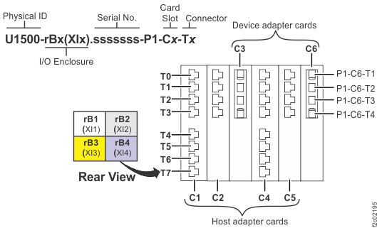
Figure 3. Rack 1-2 storage enclosure and I/O enclosure location codes (Models 982, 98F) (rear view) 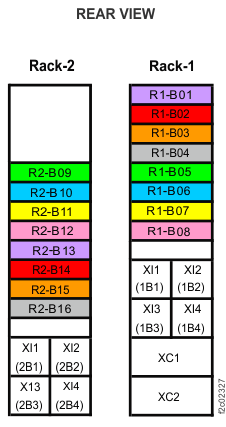
Figure 4. Rack 1-5 storage enclosure and I/O enclosure location codes (single-phase Models 981, 98E) (rear view) 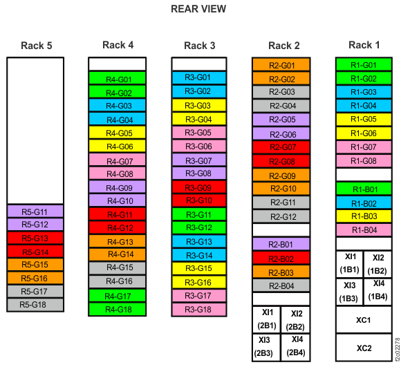
Figure 5. Rack 1-5 storage enclosure and I/O enclosure location codes (three-phase Models 981, 98E) (rear view) Note: High-performance flash enclosures are in Rack-1 and Rack-2.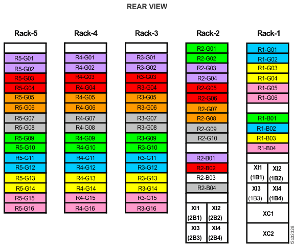
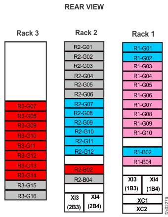
Figure 6. Rack 1-3 storage enclosure and I/O enclosure location codes (Models 980, 98B) (rear view)