MAP3400 Flash enclosure pair error during installation (Model 983)

About this task

During the installation of a DS8882 Model 983, an error was detected with a flash enclosure pair.
  • The error can be caused by one or more unplugged or misplugged SAS cables between the flash enclosure pair and the I/O enclosure.
  • The error can be caused when the upper and lower flash enclosures are installed in the wrong position relative to each other in the rack. When the 983 was preconfigured in manufacturing, the upper flash enclosure serial number was assigned to the I1-F03 location I/O enclosure SAS ports installation code. If during field installation that serial number is discovered through the I/O enclosure SAS ports for the lower location (I1-F04), it causes an error.
  • During installation, the specific error that is detected cannot be reported. Instead, all errors are reported by using one SRC and isolated with MAP3400.

MAP3400 Section-1

Procedure

  1. Determine whether each SAS flash enclosure in the pair (I1-F03, upper and I1-F04, lower) is installed in the correct rack position. See Figure 1.
    There are two methods:
    • Method one: The serial number of each enclosure is on a label at the far front right behind the snap on cover for the rack screws. Compare it to the serial number and location that are listed on the ship group parts list sheet.
    • Method two: The enclosure location code is on the rightmost label on the top front of each enclosure. The enclosure needs to be slid out far enough to display the label. The cable ties at the rear must be removed so the cables do not pull tight and get damaged.

    Are both enclosures in the proper rack positions?

    Figure 1. Locations in rack (front view)
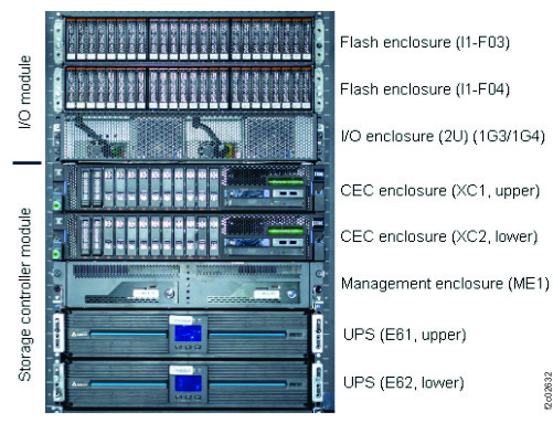
    Locations in rack (front)
  2. There are two methods to correct this install error condition. Select one.
    • Use management console service options. This option can take 2 - 4 hours to complete. Go to step 3.
    • Call the next level of support. The process might take less than an hour. They need remote access to the storage facility command line. The flash enclosures still need to be moved to the correct rack positions.
  3. The SAS flash enclosures must be moved to the correct rack positions.
    Overview of required steps to recover this condition.
    • Power off the storage facility.
    • Mechanically correct the enclosure locations in the rack and reconnect cables.
    • SF power on the storage facility.
    • Wait for the IML to complete. View storage facility state (End of Call) > LPARs IMLed (CPSS)
    • Wait for the RM harvest phase to display as complete.
    • Do a pseudo repair of the upper Flash enclosure midplane FRU.
    • Do a pseudo repair of lower Flash enclosure midplane FRU.
  4. Power off the storage facility. Refer to MAP2470 Powering off and on the storage facility from the management console.
  5. Mechanically relocate the flash enclosures in the proper rack locations.
  6. Power on the storage facility. Refer to MAP2470 Powering off and on the storage facility from the management console.
  7. View storage facility state (End of Call) > LPARs IMLed (CPSS). Refer to MAP1100 View storage facility state (end of call).
  8. Wait for the HarvestPhase process to display complete status. Go to the Service Utilities menu used in the prior step. Select View Device RM Harvest Phase.
  9. Do a pseudo repair of the Storage Enclosure Midplane FRU of the upper flash enclosure. When directed to replace the FRU, do not replace it, instead continue the repair process. Exchange Parts > Exchange Storage Enclosure and Components > Storage enclosure midplane FRU. Refer to MAP1230 Replace a FRU without using a serviceable event.
  10. Do a pseudo repair of the Storage Enclosure Midplane FRU of the lower flash enclosure.
  11. If any new related open serviceable events are created, call your next level of support.
  12. The recovery is complete. Exit this MAP.

MAP3400 Section-2

Procedure

  1. Check the SAS cable connections at upper (I1-F03) and lower (I1-F04) flash enclosures) and at the I/O enclosure (2U) (1G3/1G4). Compare the cable location code labels with the connector locations. See Figure 1, Figure 2, Figure 3, Figure 4, and Figure 5.
    Figure 2. Storage enclosure locations (rear view) (SAS flash enclosure, 24 drive slots)
    Storage enclosure locations (rear view) (SAS flash enclosure, 24 drive slots)
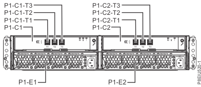
    Figure 3. Point-to-point cabling diagram for storage enclosure SAS cables (Model 983)
    Device adapter pair IDs for flash enclosures (Model 983 all-flash)
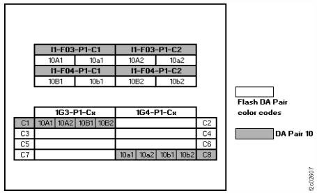
    Figure 4. Location codes, I/O enclosure (2U)
    I/O enclosure (2U) locations code (rear) (model 983) with logical IG3, 1G4
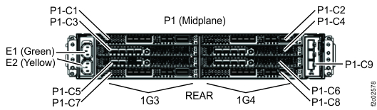
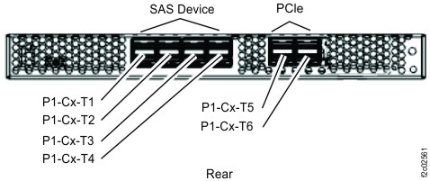
    Figure 5. Location codes, I/O enclosure (2U) adapter (PCIe, SAS device)
    Location codes, I/O enclosure (2U) adapter (PCIe, SAS device)
  2. If no SAS cable problems are found, call the next level of support. They use remote access to determine what SAS interface condition reported this error.
  3. If a SAS cable problem was not found at the I/O enclosure, go to step 7.
  4. If a cable problem was found at the I/O enclosure, select the following condition that applies.
    • One or more SAS cables with the problem are connected to the same I/O enclosure (2U) adapter (PCIe, SAS device) FRU. Go to the next step.
    • Two or more SAS cables with a problem are connected to different I/O enclosure (2U) adapter (PCIe, SAS device) FRUs. Go to step 6.
  5. Do a pseudo repair of the I/O enclosure (2U) adapter (PCIe, SAS device) FRU. (P1-C1, P1-C8, P1-C7, P1-C2). See Figure 4. When directed to replace the FRU, do not; instead, correct the SAS cable problem and continue the repair. Exit this MAP. Refer to MAP1230 Replace a FRU without using a serviceable event.
  6. Do a pseudo repair of the I/O enclosure midplane assembly FRU. (P1) See Figure 4. When directed to replace the FRU, do not; instead, correct the SAS cable problems and continue the repair. Exit this MAP. Refer to MAP1230 Replace a FRU without using a serviceable event.
  7. If a cable problem was found at the SAS flash enclosure, select the following condition that applies.
    • One or more SAS cables with the problem are connected to the same physical FRU. Go to the next step.
    • Two or more cables with a problem are connected to different physical FRUs. Go to step 9.
  8. Do a pseudo repair of the SAS flash enclosure, Enclosure service manager (ESM) FRU. (P1-C1, P1-C2) See Figure 2. When directed to replace the FRU, do not; instead, correct the cable problem and continue the repair. Exit this MAP. Refer to MAP1230 Replace a FRU without using a serviceable event.
  9. Do a pseudo repair of the SAS flash enclosure midplane FRU (P1). See Figure 2. When directed to replace the FRU, do not; instead, correct the cable problems and continue the repair. Refer to MAP1230 Replace a FRU without using a serviceable event.
  10. If the cable problem involved both flash enclosures, do a pseudo repair of the other SAS flash enclosure midplane FRU (P1).
  11. Exit this MAP.