Exchange the RPC card

Before you begin

CAUTION:
This assembly contains mechanical moving parts. Use care when you service this assembly. (C025)

Icon for electrostatic discharge wrist strapUse approved ESD procedures to prevent damage.

Attention:
  • This procedure is not a stand-alone procedure. Customer disruption and damage to the hardware might occur when microcode and power boundaries are not in the proper conditions for this service action.
  • If a serviceable event FRU repair directed you to this procedure, the microcode and power boundaries are already set.
  • If a serviceable event FRU repair did not direct you to this procedure, see MAP1230 Replace a FRU without using a serviceable event.
Notes:
  • All the cables and FRUs to be removed must be uniquely identified so they can be reinstalled correctly.
  • If an installed earthquake resistance kit prevents you from accessing this FRU, refer to MAP1600.

Remove the RPC card

Procedure

  1. To locate this FRU, take one of the following actions and then return here and continue to replace the FRU:
    • If this FRU has a FRU identify indicator, use the FRU identify indicator, which is listed in MAP1240 Locating FRUs by using identify indicators. If not, use the location code.
      Note: There might be cases where the FRU failure or fencing conditions prevent the FRU LED indicator from being lit even if the FRU has power.
    • Use the location code, which is listed in MAP1245 Finding FRUs by using location codes.
    • If there is no FRU identify indicator or location code, you were sent here by an isolation MAP or symbolic FRU procedure. Use the information in that procedure and the figures in this procedure to locate the proper part to exchange.
  2. Most, but not all, FRUs have identify indicators. Use the flashing amber or solid blue FRU identify indicators to ensure that you are working on the correct enclosure or FRU.
  3. At the front of the rack, slide the management enclosure out to the service position and remove the top cover. See Figure 1.
    Note: The management enclosure is below the two CEC enclosures.
    1. Fully loosen the left and right captive thumb screws.
    2. Slide the management out fully so the sliding rails lock into place.
    3. At the rear of the top cover, fully loosen the left and right captive thumb screws.
    4. Slide the cover back until it lifts off.
    Figure 1. Management enclosure (front)
    Front of Management enclosure (Model 983)
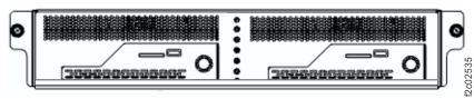
  4. Locate the RPC card (C1 or C2) to be replaced. See Figure 2. The identify LED Callout label 1 is shown in Figure 3.
    Figure 2. Management enclosure locations (Model 983)
    Management enclosure locations
    Figure 3. LEDs on the RPC card
    Management enclosure front panel
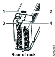
  5. At the front of the RPC card, ensure that the J1-J3 cables are properly labeled and then disconnect them. See Figure 4.
    Figure 4. RPC card locations (front)
    RPC card front connectors J1 - J3
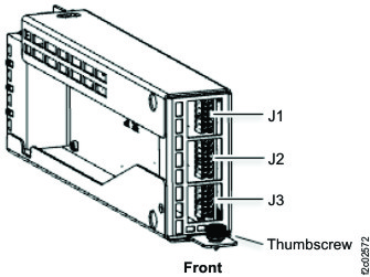
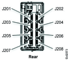
  6. At the rear of the RPC card, ensure that the J201-J208 cables are properly labeled and then disconnect them. See Figure 5.
    Figure 5. RPC card locations (rear)
    RPC card rear connectors J2xx
  7. If dust covers are present in unused connectors, remove them for reuse on the new RPC card.
  8. At the front of the RPC card, loosen the thumbscrew and then remove the RPC card. See Figure 4.

Install the RPC card

Procedure

  1. Install the new RPC card and secure it with the thumbscrew.
  2. At the rear, connect the J201-J208 cables.
  3. At the rear, install dust covers that were removed.
  4. At the front, connect the J1-J3 cables.
  5. Return the management enclosure to the operating position.
    1. Install the cover and fasten the two rear captive thumbscrews.
    2. Slide the management enclosure fully in and tighten the left and right captive thumb screws.
  6. Exit this service information center parts exchange procedure and return to the procedure that sent you here.