Exchange the PCIe cable, CEC enclosure, Model 983
Before you begin
 Use approved ESD procedures to prevent damage.
Attention:
- This procedure is not a stand-alone procedure. Customer disruption and damage to the hardware might occur when microcode and power boundaries are not in the proper conditions for this service action.
- If a serviceable event FRU repair directed you to this procedure, the microcode and power boundaries are already set.
- If a serviceable event FRU repair did not direct you to this procedure, see MAP1230 Replace a FRU without using a serviceable event.
Notes:
- All the cables and FRUs to be removed must be uniquely identified so they can be reinstalled correctly.
- If an installed earthquake resistance kit prevents you from accessing this FRU, refer to MAP1600.
Both ends of the PCIe cable use the same connector.
Remove the PCIe cable
Procedure
-
Remove the PCIe cable. Each PCIe cable goes between a CEC enclosure and an I/O enclosure
(2U).
Gently pull on the release handle and then unplug the cable.
Either end of the cable can be unplugged first. See Table 1, Table 2, Figure 1, Figure 2, Figure 3, Figure 4, and Figure 5.Note: The PCIe cable can be "hot-plugged." The FRU the cable connects to, at both ends, can stay powered on. However, the FRU on one end of the cable is quiesced and placed in service mode by the Licensed Internal Code before you are sent to this procedure.Table 1. PCIe cable connections, I/O enclosure #1, slots C1/C8 (rear) (Model 983) From CEC (upper) To I/O Enclosure (2U) P1-C7-T1 P1-C1-T5 P1-C7-T4 P1-C8-T5 From CEC (lower) To I/O Enclosure (2U) P1-C7-T1 P1-C1-T6 P1-C7-T4 P1-C8-T6 Figure 1. PCIe cable connections, I/O enclosure #1, slots C1/C8 (rear) (Model 983) 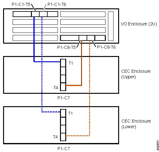
Table 2. PCIe cable connections, I/O enclosure #1, slots C2/C7 (rear) (Model 983) From CEC (upper) To I/O Enclosure (2U) P1-C7-T2 P1-C7-T5 P1-C7-T3 P1-C2-T5 From CEC (lower) To I/O Enclosure (2U) P1-C7-T2 P1-C7-T6 P1-C7-T3 P1-C2-T6 Figure 2. PCIe cable connections, I/O enclosure #1, slots C2/C7 (rear) (Model 983) 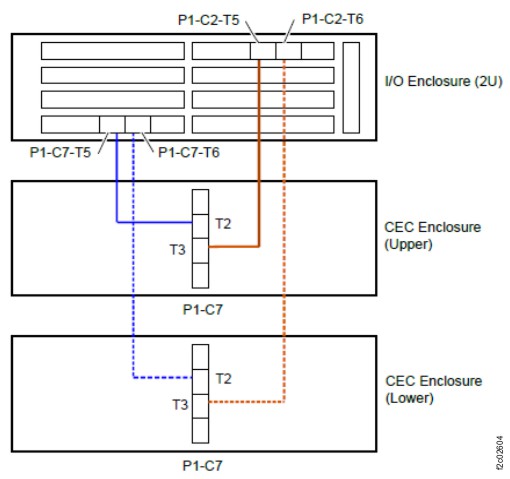
Figure 3. CEC enclosure location codes (rear view) (Models 983) 
Figure 4. I/O enclosure (2U) locations (rear) (model 983) 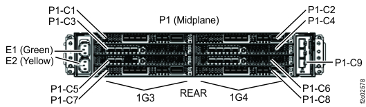
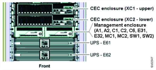
Figure 5. CEC enclosure and I/O enclosure locations in rack (rear) (model 983)