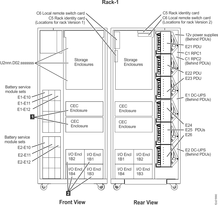
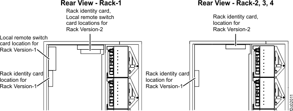
Figure 1. Identifying rack version 1 versus version 2
MAP2730 Section-1 Model 961 Rack Version 1
Procedure
Display open serviceable events and display the details
to determine the listed FRUs.
Are there any open serviceable
events listing FRUs related to the visual symptom you are here to
repair, including power distribution units (PDUs)?
Yes, exit this MAP and repair the related serviceable events.
Return here if the visual symptom still exists after all related serviceable
events have been repaired.
No, go to the next step.
At the front of Rack-1, does the management console ThinkPad laptop have
power?
MAP2730 Section-3 Unplugged or visually damaged cable
Procedure
A cable was found unplugged or visually damaged.
Note: If
more than one cable is affected, read the following procedures for
each cable to determine whether they can be repaired at the same time
or must be repaired individually. If you are not sure, do them individually.
Determine the location code to use for the pseudo repair
later in this procedure.
Use Table 1,
first column and find the fan or PJA or RPC that the unplugged or
damaged cable would be connected to.
Determine location code to use for the pseudo repair.
If your cable is for the RPC card, ensure you read Note 1 in Table 1.
Go to the next step.
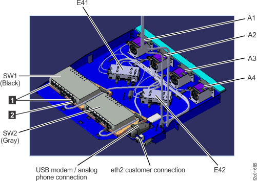
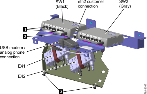
Table 1. Cable unplugged from
repair
Cable is unplugged from:
Location code to use:
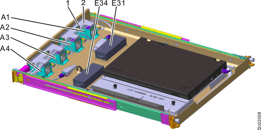
Fan A1
A1
Fan A2
A2
Fan A3
A3
Fan A4
A4
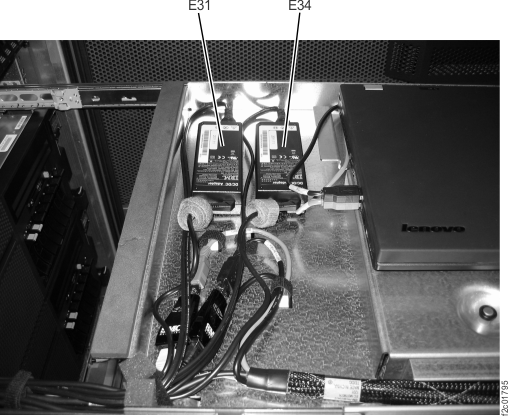
PJA, E41 (left)
E41
PJA, E42 (right)
E42
RPC-1 (upper)
E411
RPC-2 (lower)
E421
SW1 (left Ethernet switch)
2
SW2 (right Ethernet switch)
2
Notes:
1. To reconnect the Cx-J4 cable to an RPC card, you will use
the PJA location code, not the RPC location code for the pseudo repair
later in this procedure. There is no need put the entire RPC card
in service mode to reconnect this cable. Using the PJA as the service
boundary is adequate.
Is the fan FRU with the disconnected cable listed in an
open serviceable event FRU list?
Yes, use that serviceable event FRU list to do a pseudo repair
of the fan. When directed to replace the fan FRU, connect or replace
the cable as needed. If the repair failed, the timestamps of the serviceable
event will have been updated or a new related serviceable event will
have been opened. If the repair was successful, exit this MAP and
ensure all related serviceable events are closed.
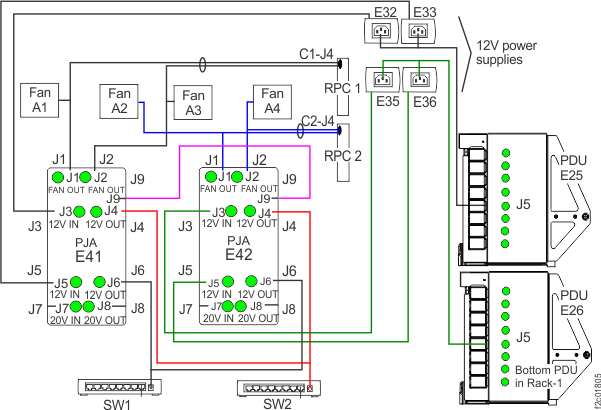
No, ensure that the PJA to PJA cable is connected to the J9
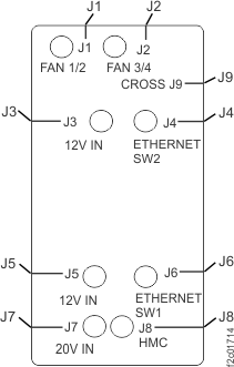
connector at both ends. E41-J1 receives power from E41-J3 and E41-J9.
There is a double fault. Return to step 1 and isolate the problem
for LED E41-J3 not lit.
No, ensure that the PJA to PJA cable is connected to the
J9 connector at both ends. E41-J2 receives power from E41-J5 and E41-J9.
There is a double fault. Return to step 1 and isolate the problem
for LED E41-J5 not lit.
The
PJA E41-J3 connector receives power from the output cable of the E32
12V power supply in the rack rear upper right. The power supply does
not have any LEDs. Ensure that the power supply input cable is plugged
and ensure that the other end is plugged to the E25-J5 PDU connector.
If the PDU E25-J5 green LED is lit, the possible failing FRUs
are the E32 12V power supply and the PDU to 12V power supply cable.
If the PDU E25-J5, J6, J7 and J8 green LEDs are not lit, there
is a problem with the lower half of the E25 PDU receiving power from
the DC-UPS DC
supply unit (DSU).
There should be an open serviceable event for that problem with MAP2710
in the FRU list. Exit this MAP and repair that serviceable event.
The
PJA E41-J5 connector receives power from the output cable of the E33
12V power supply in the rack rear upper right. The power supply does
not have any LEDs. Ensure that the power supply input cable is plugged
and ensure that the other end is plugged to the E25-J5 PDU connector.
If the PDU E25-J5 green LED is lit, the possible failing FRUs
are the E33 12V power supply and the PDU to 12V power supply cable.
If the PDU E25-J5, J6, J7 and J8 green LEDs are not lit, there
is a problem with the lower half of the E25 PDU receiving power from
the DC-UPS DC
supply unit (DSU).
There should be an open serviceable event for that problem with MAP2710
in the FRU list. Exit this MAP and repair that serviceable event.
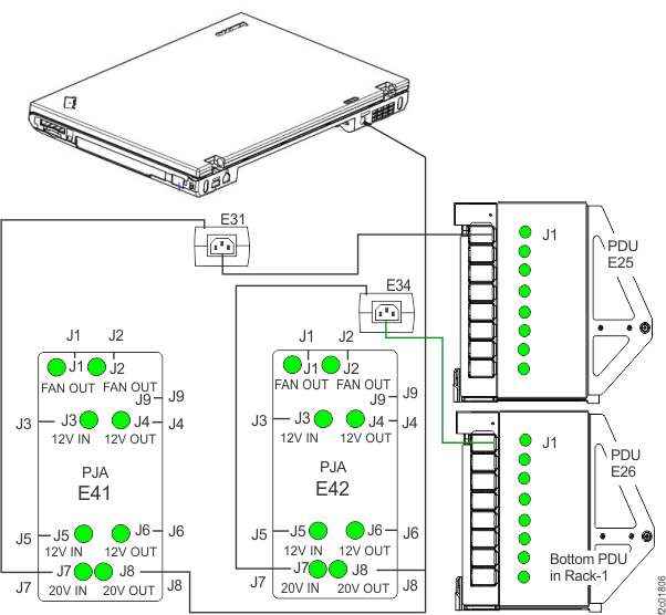
The
PJA E41-J7 connector receives power from the output cable of the E31
20V power supply on the management console tray. See Figure 4 and Figure 13. The power supply
does not have any LEDs. Ensure that the power supply input cable is
plugged and ensure that the other end is plugged to the E25-J1 PDU
connector. See Figure 13.
If the PDU E25-J1 green LED is lit, the possible failing FRUs
are the E31 20V power supply and the PDU to 20V power supply cable.
If the PDU E25-J1 green LED is not lit, and J2, J3, J4 are lit,
the PDU port fuse has failed and is not repairable. Ensure that the
output cable is not shorted to ground, and then replace the E25 PDU
by using MAP2730 Section-3 FRU replace when FRU is not listed in open
serviceable event.
If the PDU E25-J1, J2, J3 and J4 green LEDs are not lit, there
is a problem with the upper half of the E25 PDU receiving power from
the DC-UPS DC
supply unit (DSU).
There should be an open serviceable event for that problem with MAP2710
in the FRU list. Exit this MAP and repair that serviceable event.
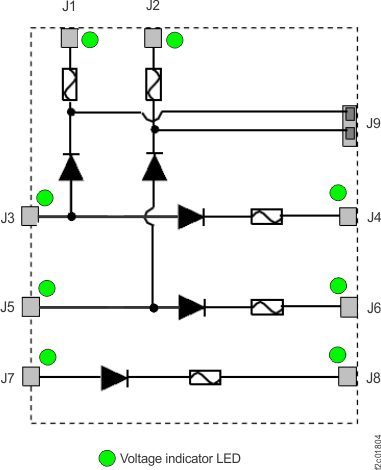
LED E41-J8 is not lit. (Figure 10) Is PJA
LED E41-J7 lit?
No, ensure the PJA to PJA cable is connected to the J9 connector
at both ends. E42-J1 receives power from E42-J3 and E42-J9. There
is a double fault. Return to step 1 and isolate the problem
for LED E42-J3 not lit.
No, ensure that the PJA to PJA cable is connected to the J9
connector at both ends. E42-J2 receives power from E42-J5 and E42-J9.
There is a double fault. Return to step 1 and isolate the problem
for LED E42-J5 not lit.
The
E42-J3 PJA connector receives power from the output cable of the E35
12V power supply in the rack rear upper right. The power supply does
not have an LED. Ensure that the power supply input cable is plugged
and ensure that the other end is plugged to the E26-J5 PDU connector.
If the PDU E26-J5 green LED is lit, the possible failing FRUs
are the E35 12V power supply and the PDU to 12V power supply cable.
If the PDU E26-J5, J6, J7 and J8 green LEDs are not lit, there
is a problem with the lower half of the E26 PDU receiving power from
the DC-UPS DC
supply unit (DSU).
There should be an open serviceable event for that problem with MAP2710
in the FRU list. Exit this MAP and repair that serviceable event.
The
E42-J5 PJA connector receives power from the output cable of the E36
12V power supply in the rack rear upper right. The power supply does
not have an LED. Ensure that the power supply input cable is plugged
and ensure that the other end is plugged to the E26-J5 PDU connector.
If the PDU E26-J5 green LED is lit, the possible failing FRUs
are the E36 12V power supply and the PDU to 12V power supply cable.
If the PDU E26-J5, J6, J7 and J8 green LEDs are not lit, there
is a problem with the lower half of the E26 PDU receiving power from
the DC-UPS DC supply unit (DSU). There should be an open serviceable
event for that problem with MAP2710 in the FRU list. Exit this MAP
and repair that serviceable event.
The
PJA E42-J7 connector receives power from the output cable of the E34
20V power supply on the management console tray. See Figure 4 and Figure 13. The power supply
does not have any LEDs. Ensure that the power supply input cable is
plugged and ensure that the other end is plugged to the E26-J1 PDU
connector. See Figure 13.
If the PDU E26-J1 green LED is lit, the possible failing FRUs
are the E34 20V power supply and the PDU to 20V power supply cable.
If the PDU E26-J1, J2, J3 and J4 green LEDs are not lit, there
is a problem with the upper half of the E26 PDU receiving power from
the DC-UPS DC supply unit (DSU). There should be an open serviceable
event for that problem with MAP2710 in the FRU list. Exit this MAP
and repair that serviceable event.
LED E42-J8 is not lit. (Figure 10) Is PJA
LED E42-J7 lit?
J8 green LED is not lit on both PJAs. There is a separate
problem for each PJA that must be fixed. Go to MAP2730 Section-5 PJA LED not lit.
Figure 13. 20V power distribution (Power
connects to right side of some laptop models)
The laptop should
automatically power on when customer power is present and the DC-UPS DC supply
unit (DSU)
mainline input circuit breakers CB1 are on (up). There is a small
accessory card plugged into the docking connector on the bottom of
the laptop that
provides this function. Go to MAP6000 Entry point for analyzing management console problems.
 . See Figure 2.