MAP2820 Local/remote jumper-setting is different between RPC cards (Model 983)
The management console received an interrupt
from an RPC card that shows the Local/Remote
Switch setting changed and the switch setting is now being reported as different between the two
RPCs.
About this task
The actual failure could be one of the following scenarios:
Scenario 1: The switch-setting was changed, but one of the RPC cards does not report the
change.
Scenario 2: The switch-setting was not changed, but one of the RPC cards falsely reports a
change.
Note: When only one RPC card reports a change to the switch setting,
the reported change might be true or false. Use this MAP to determine the switch
setting.
MAP2820 Section-1
Procedure
This MAP might require you to know the SRC or FRU locations from the serviceable event. If you
do not know them, display them now by using the following steps:
At the top of this MAP procedure, click Close.
To the question What was the result of using the service procedure? click
Delay the repair and then click Next.
The selected serviceable event is displayed. Under Selected, click View
Details.
Record notes or take a picture of the information. Then, click
Cancel.
The selected serviceable event is displayed.
Begin the repair to return to this MAP procedure.
Determine and record which RPC card is fenced.
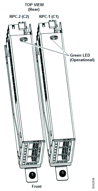
The RPC-1 and RPC-2 cards are at the rear of the Management enclosure (Figure 1). To observe the green operational LED on
top of the RPC card, slide the management enclosure into the service position at the front of the
rack. Then, remove the cover (loosen the two rear captive thumbscrews).
Observe the green LED on both RPC cards (Figure 2).
Proceed as if RPC-1 (C1) is fenced. Go to the next step.
On
On
BE193110 or BE19030C
Proceed as if RPC-2 (C2) is fenced. Go to the next step.
On
On
Not one of the following: BE193110, BE193111 BE19030A,
BE19030C
No visual symptom to repair. Exit this procedure and repair the serviceable event that sent
you here.
Off
On
Any
Record that the RPC-1 (C1) card is fenced.
Go to the next step.
On
Off
Any
Record that the RPC-2 (C2) card is fenced.
Go to the next step.
Off
Off
Any
Invalid condition. Exit this procedure and repair any related open serviceable events.
Figure 1. Management enclosure locations (Model 983)Figure 2. LEDs on the RPC cards (Model 983)
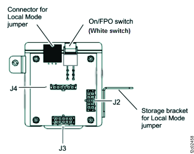
Record the physical setting of the Local/Remote jumper on the Local remote jumper card.
The setting is Local if the jumper is inserted in the LR jumper card connector.
Note: The jumper design requires it be removed from the connector to allow the enclosure cover to
be installed. The jumper is stored in the bracket.
The setting is Remote if the jumper is not in the LR jumper card connector.
Display and record the setting of the Local/Remote jumper as reported by the management
console.
From the navigation area, click Storage Facility Management > storage facility.
From the bottom Task area, click Service Utilities > Storage Facility Power Control. The Power Control window opens.
At the top left of the screen, record the setting of the Current Local/Remote jumper
state.
Note: For SRCs BE193110, BE193111, BE19030A, and BE19030C: If you receive the error message, "Unable
to find storage facility power state.", dismiss the error. Assume that the reported setting of the
jumper matches the physical setting and continue.
Use the results from the steps above and find the row in Table 2 that matches your condition. Then, use the
last column to continue the repair.
Table 2. Repair action for fenced or failing RPC cards
Fenced RPC card (Green LED off) or the SRC that called out this MAP: (From steps
1 and 2.)
LR card jumper is physically set to: (From step 3.)
The RPC-1 card (C1) incorrectly reports the Local/Remote jumper-setting. The jumper-setting is
Local and the last setting the management console detected was Local, so the failure caused the
RPC-1 card (C1) to incorrectly report the jumper-setting as Remote. Use the FRU replace option to
replace the following FRUs in the order listed. (Refer to MAP1230 Replace a FRU without using a serviceable event.)
RPC-1 (C1) card
Cable between the RPC-1 (C1) card J3 and local remote jumper card J2 cable. (See Figure 3, Figure 4, Figure 5.)
Note: The cable is not listed as a FRU. Instead, select the RPC-1 (C1) card when directed to replace
it, replace the cable.
Local remote jumper card.
Figure 3. Local remote jumper card to RPC cards and operator panel LEDs cableFigure 4. Local remote jumper card, rear viewFigure 5. Locale remote switch card to RPC cards and Operator panel LEDs cable
MAP2820 Section-3
Procedure
The RPC-2 (C2) card incorrectly reports the jumper state. The jumper-setting changed to remote,
but the RPC-2 (C2) card does not report the jumper change. Complete the following
steps:
Change the Local/Remote setting to Local. Insert the jumper into the local remote jumper card
connector.
Use the utility option to System Level Deactivate and then System Level Activate the RPC-1 (C1) card. Storage Facility Management > storage facility > Service Utilities > Activate/Deactivate Resources > Show Rack Enclosures > (select rack) > U2xxx.xxx.sssssss-C1 (Rack power Control (RPC) Card, State: available > System Level Deactivate
Use the FRU replace option to replace the following FRUs in the order listed. For each FRU
being replaced, after fix verification completes, change the Local/Remote jumper-setting to Remote.
(Refer to MAP1230 Replace a FRU without using a serviceable event.)
RPC-2 (C2) card
Cable between the RPC-2 (C2) card J3 and local remote jumper card J3 cable. (See Figure 3.)
Note: The cable is not listed as a
FRU, instead select the RPC-2 (C2) card when directed to replace it, replace the cable.
Local remote jumper card.
Observe the RPC-1 (C1) card green LED. Is the green LED lit?
Yes, both RPC cards are operational; the failure is repaired. Exit this MAP and close the
serviceable event. For details, see MAP1235 Section-2, Exit Procedure 1: Problem
fixed.
No, the original failure reoccurred. Go to MAP2820 Section-3
step 1 and replace the next FRU in
the list.
MAP2820 Section-4
Procedure
The RPC-2 (C2) card incorrectly reports the local remote jumper-setting. The management console
still reports that the jumper-setting is Remote, but the actual jumper-setting is Local. That
indicates the jumper-setting was changed from Remote to Local and the RPC-2 (C2) card is still
reporting a Remote jumper-setting. Do the following actions to further isolate the cause of the
failure:
Change the local remote jumper-setting to Remote (unplug the jumper from the card and place it
in the storage bracket. The two RPCs detect this change and make the jumper-setting agree.
Use the utility option to System Level Deactivate and then System Level Activate the RPC-1 (C1)
card so that the fence is reset and it becomes operational (the green LED is lit). Storage Facility Management > storage facility > Service Utilities > Activate/Deactivate Resources > Show Rack Enclosures > (select rack) > U2xxx.xxx.sssssss-C1 (Rack power Control (RPC) Card, State: available > System Level Deactivate
Use the utility option to System Level Deactivate the RPC-2 (C2) card.
Change the local remote jumper-setting back to Local (plug the jumper into the card
connector).
Disconnect the cable at J3 on the RPC-2 (C2) card. When the cable is disconnected, the signal
from the jumper reports that the jumper is in the Local position.
Use the utilities to System Level Activate the RPC-2 (C2) card.
Observe the RPC-2 (C2) card green LED. Is the green LED lit?
Disconnect the cable at J3 on the local remote jumper card.
Reconnect the cable at J3 on RPC-2 (C2) card.
Go to the next step.
Observe the RPC-2 (C2) card green LED. Is the green LED lit?
Yes, RPC-2 (C2) card is not fenced; the Local remote jumper card is failing. Use the replace
FRU option to replace the Local remote jumper card. For
details, see MAP1235 Section-3, Exit Procedure 2:
Problem isolated, exchange FRU.
No, RPC-2 (C2) card is fenced again and the cable between RPC-2 (C2) card and the Local
remote jumper card is failing. Use the replace FRU option to replace the cable. (Refer to MAP1230 Replace a FRU without using a serviceable event. The cable is not listed as a FRU; instead,
select the RPC-2 (C2) card when directed to replace it, replace the cable.) For details, see MAP1235 Section-3, Exit Procedure 2: Problem isolated,
exchange FRU.
MAP2820 Section-5
Procedure
The RPC-1 (C1) card incorrectly reports a jumper-setting change to Remote. The jumper-setting
is Remote and the last setting the management console detected was Remote, so the failure caused the
RPC-1 (C1) card to incorrectly report the jumper-setting as Local. The cable between the RPC-1 (C1)
card and the local remote jumper card might be loose or disconnected. Do the following
tasks:
Inspect and correct any problems for the cable connector J2 on the local remote jumper
card.
Inspect and correct any problems for the cable at connector J3 on the RPC-1 card.
Did you find a cable problem and correct it?
Yes, to verify the repair, go to the next step.
No, go to the next step.
Use the utility option to System Level Deactivate and then System Level Activate the RPC-1 (C1) card. Storage Facility Management > storage facility > Service Utilities > Activate/Deactivate Resources > Show Rack Enclosures > (select rack) > U2xxx.xxx.sssssss-C1 (Rack power Control (RPC) Card, State: available > System Level Deactivate
Note: Repeat the same menu steps to perform System Level Activate.
If the System Level Activate is successful, the failure is repaired. Exit this MAP and close
the serviceable event. For details, see MAP1235 Section-2, Exit Procedure 1: Problem
fixed.
If the System Level Activate fails, go to the next step.
Yes, exit this MAP and close the original serviceable event. For details, see MAP1235 Section-2,
Exit Procedure 1: Problem fixed.
No, go to the next step.
Use the replace FRU option to replace the cable between the RPC-1 (C1) card and the local
remote jumper card. (Refer to MAP1230 Replace a FRU without using a serviceable event.) (The
cable is not listed as a FRU. Instead, select the RPC-1 (C1) card when directed to replace it,
replace the cable.) Was the FRU verification successful?
Yes, exit this MAP and close the original serviceable event. For details, see MAP1235 Section-2,
Exit Procedure 1: Problem fixed.
No, go to the next step.
Change the local remote jumper to the Local setting (installed in the local remote jumper card
connector).
Use the replace FRU option to replace the Local remote jumper card. When the local remote
jumper card replacement is complete, return the local remote jumper-setting to the Remote setting
(in the storage bracket). After the repair completes, exit this MAP and close the serviceable
event. For details, see MAP1235 Section-3, Exit Procedure 2: Problem isolated,
exchange FRU.
MAP2820 Section-6
Procedure
The RPC-2 card (C2) incorrectly reports the Local/Remote jumper-setting. The jumper-setting is
Local and the last setting the management console detected was Local, so the failure caused the
RPC-2 card (C2) to incorrectly report the jumper-setting as Remote. Use the FRU replace option to
replace the following FRUs in the order listed. (Refer to MAP1230 Replace a FRU without using a serviceable event.)
RPC-2 (C2) card
Cable between the RPC-2 (C2) card J3 and local remote jumper card J3 cable. (See Figure 3, Figure 4, Figure 5.)
Note: The cable is not listed as a FRU. Instead, select the RPC-2 (C2) card when directed to
replace it, replace the cable.
Local remote jumper card.
MAP2820 Section-7
Procedure
The RPC-1 (C1) card incorrectly reports the jumper state. The jumper-setting changed to remote,
but RPC-1(C1) card does not report the jumper change. Do the following tasks:
Change the Local/Remote setting to Local. Insert the jumper into the local remote jumper card
connector.
Use the utility option to System Level Deactivate and then System Level Activate the RPC-2 (C2) card. Storage Facility Management > storage facility > Service Utilities > Activate/Deactivate Resources > Show Rack Enclosures > (select rack) > U2xxx.xxx.sssssss-C2 (Rack power Control (RPC) Card, State: available > System Level Deactivate
Use the replace FRU option to replace each of the FRUs in the order listed. For each FRU being
replaced, after fix verification completes, change the Local/Remote jumper-setting to Remote. (Refer
to MAP1230 Replace a FRU without using a serviceable event.)
RPC-1 (C1) card
Cable between the RPC-1 (C1) card and the Local remote jumper card. (The cable is not listed as
a FRU. Instead, select the RPC-1 (C1) card when directed to replace it, replace the cable.)
Local remote jumper card
Observe the RPC-2 (C2) card green LED.
Yes, both RPCs are operational, and the failure is repaired. Exit this MAP and close the
serviceable event. For details, see MAP1235 Section-2, Exit Procedure 1: Problem
fixed.
No, the original failure reoccurred. Return to MAP2820 Section-3 step 1 and replace the next FRU
in the list.
MAP2820 Section-8
Procedure
The RPC-1 (C1) card incorrectly reports the local remote jumper-setting. The management console
still reports that the jumper-setting is Remote, but the actual jumper-setting is Local. The
jumper-setting was changed from Remote to Local, and the RPC-1 (C1) card still reports a Remote
jumper-setting. Do the following actions to further isolate the cause of the
failure:
Change the local remote jumper-setting to Remote (unplug the jumper from the card and place it
in the storage bracket. The two RPCs detect this change and make the jumper-setting agree.
Use the utility option to System Level Deactivate and then System Level Activate the RPC-1 (C1)
card so that the fence is reset and it becomes operational (the green LED is lit). Storage Facility Management > storage facility > Service Utilities > Activate/Deactivate Resources > Show Rack Enclosures > (select rack) > U2xxx.xxx.sssssss-C1 (Rack power Control (RPC) Card, State: available > System Level Deactivate
Use the utility option to System Level Deactivate the RPC-1 (C1) card.
Change the local remote jumper-setting back to Local (plug the jumper into the card
connector).
Disconnect the cable at J3 on the RPC-1 (C1) card. After you disconnect the cable, the signal
from the jumper reports that the jumper is in the Local position.
Use the utilities to System Level Activate the RPC-1 (C1) card.
Observe the RPC-1 (C1) card green LED. Is the green LED lit?
Disconnect the cable at J2 on the local remote jumper card.
Reconnect the cable at J3 on RPC-1 (C1) card.
Go to the next step.
Observe the RPC-2 (C2) card green LED. Is the green LED lit?
Yes. RPC-2 (C2) card is not fenced, and the Local remote jumper card is failing. Use the
replace FRU option to replace the Local remote jumper card. For details, see MAP1235 Section-3, Exit
Procedure 2: Problem isolated, exchange FRU.
No. RPC-2 (C2) card is fenced again, and the cable between RPC-2 (C2) card and the Local
remote jumper card is failing. Use the replace FRU option to replace the cable. (Refer to MAP1230 Replace a FRU without using a serviceable event. The cable is not listed as a FRU. Instead,
select the RPC-2 (C2) card when directed to replace it, replace the cable.) For details, see MAP1235 Section-3, Exit Procedure 2: Problem isolated,
exchange FRU.
MAP2820 Section-9
Procedure
The RPC-2 (C2) card incorrectly reports a jumper-setting change to Remote. The jumper-setting
is Remote and the last setting the management console detected was Remote, so the failure caused the
RPC-2 (C2) card to incorrectly report the jumper-setting as Local. The cable between the RPC-2 (C2)
card and the local remote jumper card might be loose or disconnected. Do the following
tasks:
Inspect and correct any problems for the cable connector J3 on the local remote jumper
card.
Inspect and correct any problems for the cable at connector at J3 on the RPC-2 (C2) card.
Did you find a cable problem and correct it?
Yes, to verify the repair, go to the next step.
No, go to the next step.
Use the utility option to System Level Deactivate and then System Level Activate the RPC-2 (C2) card. Storage Facility Management > storage facility > Service Utilities > Activate/Deactivate Resources > Show Rack Enclosures > (select rack) > U2xxx.xxx.sssssss-C2 (Rack power Control (RPC) Card, State: available > System Level Deactivate
Note: Repeat the same menu steps to perform System Level Activate.
If the System Level Activate is successful, the failure is repaired. Exit this MAP and close
the serviceable event. For details, see MAP1235 Section-2, Exit Procedure 1: Problem
fixed.
If the System Level Activate fails, go to the next step.
Yes, exit this MAP and close the original serviceable event. For details, see MAP1235 Section-2,
Exit Procedure 1: Problem fixed.
No, go to the next step.
Use the replace FRU option to replace the cable between RPC-2 card and the local remote jumper
card. (Refer to MAP1230 Replace a FRU without using a serviceable event. The cable is not listed
as a FRU. Instead, select the RPC-2 (C2) card when directed to replace it, replace the
cable.) Was the FRU verification successful?
Yes, exit this MAP and close the original serviceable event. For details, see MAP1235 Section-2,
Exit Procedure 1: Problem fixed.
No, go to the next step.
Change the Local/Remote jumper to the Local setting.
Use the replace FRU option to replace the local remote jumper card. When the local remote
jumper card replacement is complete, return the Local/Remote jumper-setting to the Remote setting.
After the repair completes, exit this MAP and close the serviceable event. For details, see MAP1235 Section-3,
Exit Procedure 2: Problem isolated, exchange FRU.