The network topology tool displays information about the
networks that are associated with the storage facility. This
MAP provides guidance on using the tool when directed from the maintenance
package or next level of support.
MAP7001 Section-2 (Invoking the network topology tool)
Procedure
From the navigation
area, click HMC Management.
In the
right work area, go to the Operations section
and click View Network Topology.
Wait several minutes for the tool to gather and present
the results. For examples of the screens that are displayed by the
network topology tool, see MAP7001 Section-3 (Examples of screens),
and then return here and go to the next step.
Screens that contain information about the network topology
are displayed when you invoke the network topology tool.
Procedure
Figure 1 shows
the Network Topology window. The current network
topology is listed at the top of the window; the saved network topology
listed at the bottom. Figure 2 shows
the upper left area of the window. This area looks different depending
on the configuration of the storage facility.
Figure 1. Network Topology window (Current Topology area is shown)
Figure 2. Topology example 9x1 with one
MC
Notes:
Examples of nodes include:
Local HMC ports
HMC ports on a second HMC (if installed)
Service processor ports
LPAR (partition) ports on the CEC enclosure I/O backplane assembly, CEC enclosureVPD pass-through card, or
PCI Ethernet card / CEC enclosure Ethernet two-port
card
The tool provides a hierarchical view of the network from the management console which
you logged onto.
The Current Topology view (upper half of the window) shows the
status of detected nodes on each of the two storage facility private
networks at the time the tool was invoked or when Refresh was
selected.
The Saved Topology view (lower half of the window) shows the status
of nodes when the Save function was last performed. A Save should
have been performed during installation of the management console or after
a repair to a FRU which is connected to the network. Normally, the
saved topology will represent the network status when all nodes on
both private networks were fully present and operational.
To verify connectivity to a failing node, ping the selected node
by clicking the Ping Current Node button (Current
Topology view) or the Ping Saved Node button
(Saved Topology view).
The service processors (represented by
"FSP" in the Network Topology window) are accessed through one
of the two networks, so they will not appear on both. This is normal.
The service processors are accessed by MC 1 through the GRAY network (172.17.x.x).
The service processors are accessed by MC 2 through the BLACK network (172.16.x.x).
The CEC enclosure (or
Storage Facility system) status information is displayed along with
the associated service processor, so will not appear on both networks. This is normal.
The LPAR status will be displayed under the CEC enclosure. However,
you must ping the LPARs by selecting the icon that is listed separately
from the CEC enclosure.
When you have resolved all network problems, perform a Save for
future comparison.
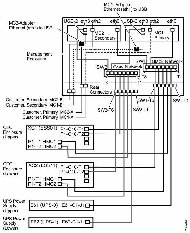
Figure 4. Diagram of network topology (Models 98x, not 983)Figure 5. Diagram of network topology (Model 983)
MAP7001 Section-4 (Analyzing the results and repairing the
network)
Procedure
Are there two management consoles?
Yes, repeat Section-2 on the other management console, and then go to the next step.
No, go to the next step.
Compare the current topology with the saved topology to verify connectivity with all nodes on
the storage facility private network.
If there are two management consoles, compare the topology on both. Are all expected
nodes present and operational on all management consoles?
Yes, exit this MAP and return to the procedure that sent you here.
No, make a note of the failing nodes, then go to the next step.
If you are using this step for verification and have identified
that all problems are now resolved, click the Save button
to save the current topology information for future use.
Table 2 contains
a list of possible results that you might have seen when you used
the network topology tool. Find the condition that describes the current
status of the network and take the appropriate action.
Table 2. Results of the topology test
Result of the topology test
Action
One management console has lost
connectivity to all nodes through both networks (Black/eth0 and Gray/eth3).
One or both management consoles have lost connectivity to all nodes
on a single storage facility (both CEC enclosures)
through both networks (Black/eth0 and Gray/eth3).
One or both management consoles have lost connectivity to all nodes
(service processor and LPARs)
on a single CEC enclosure (one of the two processor complexes in a storage facility) through both
networks (Black/eth0 and Gray/eth3).
One or both management consoles have lost connectivity to the service processor on a single CEC
enclosure (one of the two processor complexes in a storage facility) through both networks
(Black/eth0 and Gray/eth3).
One or both management consoles have lost connectivity to an LPAR on
a single CEC enclosure (one of the two processor complexes in a storage facility) through both
networks (Black/eth0 and Gray/eth3).
One or both management consoles have lost connectivity to all nodes
on a single storage facility (both CEC enclosures)
through interface eth0 (Black network).
One or both management consoles have lost connectivity to all nodes
(service processor and LPARs)
on a single CEC enclosure (one of the two processor complexes in a storage facility) through
interface eth0 (Black network).
One or both management consoles have lost connectivity to the service processor on a single CEC
enclosure (one of the two processor complexes in a storage facility) through interface eth0 (Black
network).
One or both management consoles have lost connectivity to an LPAR on
a single CEC enclosure (one of the two processor complexes in a storage facility) through interface
eth0 (Black network).
One or both management consoles have lost connectivity to all nodes
on a single storage facility (both CEC enclosures) through interface eth3 (Gray network).
One or both management consoles have lost connectivity to all nodes
(service processor and LPARs)
on a single CEC enclosure (one of the two processor complexes in a storage facility) through
interface eth3 (Gray network).
One or both management consoles have lost connectivity to the service processor on a single CEC
enclosure (one of the two processor complexes in a storage facility) through interface eth3 (Gray
network).
One or both management consoles have lost connectivity to an LPAR on
a single CEC enclosure (one of the two processor complexes in a storage facility) through interface
eth3 (Gray network).