MAP7011 Private network isolation procedure 11
The Network Topology tool determined that one management console lost connectivity to all nodes through the SW1 Ethernet switch (Black network) eth0 port.
MAP7011 Section-1
Procedure
-
Select the appropriate rack model:
- 983: go to MAP7011 Section-9.
- All models except 983: go to the next step.
- Locate the Ethernet switch SW1 (black network) at the rear
of the storage facility that
contains the failing management console. See Figure 1 for 16-port switches,
and Figure 2, Figure 3, and Figure 4 for 8-port switches.
Is the Ethernet switch powered on?Note: If this management console is an external management console, then go to the storage facility to which the management console is cabled.
- Yes, continue with the next step.
- No, go to MAP2350 Ethernet switch power problem.
Figure 1. 16-port Ethernet switch port designations (SW1, SW2 - Tx) - Models 921/931, 922/932, 9A2/9B2 
Figure 2. 8-port Ethernet switch port designations (SW1, SW2-Tx) Models 921/931, 922/932, 9A2/9B2 
Figure 3. 8-port Ethernet switch port designations (SW1, SW2-Tx) Model 941, Model 951, and Model 961 
Figure 4. 8-port Ethernet switch port designations (SW1, SW2-Tx) Models 98x 
- Select the type of Ethernet switches in the affected storage facility:
- Observe the 16-port Ethernet switch
port LEDs for the failing management console link (SW1-T1
for HMC1 or SW1-T2 for HMC2). See Figure 1. See Table 1 for a description and interpretation of the Ethernet Switch port LEDs.
Table 1. 16-port Ethernet switch port LED descriptions LED State Meaning Upper On 1000 Mb/s connection Off 100 Mb/s connection (Normal for FSP connection only) Lower Off No link On Link, No Activity Flashing Link, Activity There are two LEDs for each port.
Is the lower Link LED lit solidly or flashing?- Yes, continue with step 9.
- No, continue with the next step.
- Temporarily move the Ethernet cable to an unused port on
the same switch. Observe the Ethernet switch port LEDs corresponding
to the new location. Is the lower Link LED lit solidly or flashing?
- Yes, apparently the Ethernet switch is failing. Move the Ethernet cable back to its original port and then go to MAP7011 Section-5.
- No, move the Ethernet cable back to its original port and go to step 9.
- Observe the 8-port Ethernet switch
port LEDs for the failing management console link (SW1-T1 for HMC1
or SW1-T2 for HMC2). See Figure 2.
- When viewed from the rear of the rack, the Ethernet ports are numbered 1 - 8 from right to left. The LED indicator for each port is on the top front edge of the switch and are also numbered T1 to T8 from right to left.
- See Table 2 for a description and interpretation of the 8-port Ethernet switch port LEDs.
Table 2. 8-port Ethernet switch port LED description LED State Meaning Blue port LED Off No link On Link, No Activity Flashing Link, Activity Is the blue port LED lit solidly or flashing?- Yes, continue with step 9.
- No, continue with the next step.
- Is there an unused port on the same switch?
- Yes, go to the next step.
- No, temporarily unplug the cable from port T8, and then continue with the next step.Note: For models 9A2 and 9B2, unplugging the cable might cause a new serviceable event to be opened for Ethernet communications from the second LPAR on this CEC enclosure. After this cable is reconnected in the following step, you can close that serviceable event.
- Temporarily move the Ethernet cable to an unused
port on the same switch. Observe the Ethernet switch port LEDs corresponding
to the new location. Is the port LED lit solidly or flashing?
- Yes, apparently the Ethernet switch is failing. Move the Ethernet cable back to its original port. If you unplugged the cable from T8 to create an unused port, then reconnect that cable now. Then, go to MAP7011 Section-5.
- No, move the Ethernet cable back to its original port and continue with the next step.
- Select the step that applies to your management console:
- Observe the eth0 link status LED on the rear
of the failing management console.
See Figure 5 (X335 server)
or Figure 6 (X336 server) or Figure 7 (X3550
server). Is the eth0 Link Status LED lit?
- Yes, continue with MAP7011 Section-2.
- No, continue with the next step.
Figure 5. LEDs on the rear of the X335 management console server 
Figure 6. LEDs on the rear of the X336 management console server 
Figure 7. LEDs on the rear of the X3550 management console server 
- Move the Ethernet cable from eth0 to eth1. See Figure 8 (X335 server)
or Figure 11 (X336
server) or Figure 12 (X3550 server). Is the eth1 Link Status LED lit?
- Yes, apparently the management console Ethernet port is failing. Restore the Ethernet cables to their original positions and continue with MAP7011 Section-3.
- No, apparently the Ethernet cable between the management console and Ethernet switch is failing. Go to MAP7011 Section-6 to replace the cable.
Figure 8. Ethernet connectors on the rear of the X335 management console server 
Figure 9. Ethernet connectors on the rear of the X336 management console server 
Figure 10. Ethernet connectors on the rear of the X336 management console server 
Figure 11. Ethernet connectors on the rear of the X336 management console server 
Figure 12. Ethernet connectors X3550 management console server (rear view) 
- Observe the eth0
USB Ethernet 100/ACT LED indicator. See Figure 15.
- The eth0 USB Ethernet adapter USB cable connects to the ThinkPad W500 as shown in Figure 14.
- The USB and Ethernet cables that connect to the eth0 adapter are black. See Figure 13.
Figure 13. eth0 (black network) and eth3 (gray network) USB Ethernet adapters for Thinkpad W500 (similar for Thinkpad T510, T520, T530, T540) 
Figure 14. Ethernet connector eth0 for laptop management console (rear view) 
Figure 15. USB Ethernet adapter LED indicators 
Is the indicator lit or blinking?
- Yes, the Ethernet connection appears to be working. Exit this MAP and determine whether the failure is still occurring.
- No, go to step 15.
- Observe
the eth0 USB Ethernet 100/ACT LED indicator. See Figure 15.
- For T510, T520, and T530, the eth0
Ethernet adapter USB cable connects to the left side, upper USB connector
as shown in Figure 16. - For T540, the eth0 Ethernet adapter
USB cable connects to the left side, front USB connector
as shown in Figure 17. - The USB and Ethernet cables that connect to the eth0 adapter are black. See Figure 13.
Figure 16. ThinkPad T510, T520, and T530 USB and RJ45 network connection ports 
Figure 17. ThinkPad T540 laptop unit cable connections (left and rear) 
Is the indicator lit or blinking?
- Yes, the Ethernet connection appears to be working. Exit this MAP and determine whether the failure is still occurring.
- No, go to step 15.
- For T510, T520, and T530, the eth0
Ethernet adapter USB cable connects to the left side, upper USB connector
- For Model
98x: observe the eth0 link status LED on the rear of the failing management
console. See Figure 18.
Is the eth0 Link Status LED lit?
- Yes, the Ethernet connection appears to be working. Exit this MAP and determine whether the failure is still occurring.
- No, complete the following steps:
- Ensure that the private network cable is properly connected to the model 98x management console and the network switch.
- If the cable is properly connected, then try another network cable before you replace the model 98x management console.
- Continue with MAP7011 Section-3.
Figure 18. Ethx and Ethx LEDs on the rear of the model 98x management console server Notes:- Ethernet ports: eth3 2 ; eth2 3 ; eth0 4 . The Ethernet port LED activity is the same format (left-right LED status) as in this figure.
- The eth3 and eth2 LEDs have the Activity LED on the left and Link Status (speed) LED on the right.
- The eth0 LEDs have the Activity LED on right and Link Status (speed) LED on the left.

- Perform
the following steps:
- Ensure that the eth0 USB Ethernet adapter is properly connected to the laptop middle USB port. See Figure 14.
- Ensure that the private network cable is properly connected to the USB Ethernet adapter.
- If the cables are properly
connected, the possible failing FRUs are the:
- USB Ethernet adapter, private network cable, or USB cable, all three of which can be replaced concurrently.
- USB port on the laptop, which requires replacing the laptop.
MAP7011 Section-2
In this section, you attempt to resolve the problem by performing a network reset on the failing management console network port.
Procedure
Is the network problem resolved?
- Yes, return to the serviceable event and close it by reviewing the steps in MAP1500 Ending a service action.
- No, replace the FRUs in the order that is listed in Table 3 until the problem is resolved.
| FRU | Go to: |
|---|---|
| Management console Ethernet adapter | MAP7011 Section-4 |
| Ethernet switch | MAP7011 Section-5 |
| Cable, management console to Ethernet switch | MAP7011 Section-6 |
MAP7011 Section-3
In this section, you attempt to resolve the problem by performing a network reset on the failing management console network port.
Procedure
Is the network problem resolved?
- Yes, return to the serviceable event and close it by reviewing the steps in MAP1500 Ending a service action.
- No, if you have an x335, x336 or x3550 HMC, go to MAP7011 Section-4 to replace the Ethernet adapter in the management console server.
- No, if you have a ThinkPad laptop, go to MAP7011 Section-7 to replace one of the following FRUs:
- eth0 Ethernet adapter
- USB cable
- ThinkPad laptop (the laptop system board is not a FRU, it takes too long to replace)
- No, if you have a model 98x management console, go to MAP7011 Section-8 to replace the management console.
MAP7011 Section-4
In this section, you replace the xSeries HMC Ethernet adapter eth0 to correct problems with the Black network.
Procedure
- Ensure that the customer is not currently accessing the management console to perform a logical configuration of Copy Service functions. The management console is powered off to replace the Ethernet card.
- Open the appropriate manual that is contained on the IBM
DS8000® series Service Documents
CDROM:
- xSeries 335 Type 8676, Type 8830 Hardware Maintenance Manual and Troubleshooting Guide
- xSeries 336 Type 1879 and Type 8837 Hardware Maintenance Manual and Troubleshooting Guide
- IBM System x3550 Type 7978 and 1913 Problem Determination and Service Guide
- Using the appropriate manual, replace the management console Ethernet
adapter that is associated with eth0.
- Power off the server. (Refer to the "General information" section.)
- Replace the Ethernet card. (Refer to the "Customer replaceable units" section.)
- Power on the server (Refer to the "General information" section.)
-
Verify the fix by using the Network Topology test tool as described in MAP7001 Using the network topology tool. Is the network problem resolved?
- Yes, return to the serviceable event and close it by reviewing the steps in MAP1500 Ending a service action.
- No, if you have other FRUs to replace, then continue with the replacement. Otherwise, contact your next level of support.
MAP7011 Section-5
In this section, you replace the SW1 Ethernet switch to correct problems with the Black network.
Procedure
- Go to Exchanging parts to replace the SW1 Ethernet switch. Return here after the Ethernet switch is replaced.
-
Verify the fix by using the Network Topology test tool as described in MAP7001 Using the network topology tool. Is the network problem resolved?
- Yes, return to the serviceable event and close it by reviewing the steps in MAP1500 Ending a service action
- No, if you have other FRUs to replace, then continue with the replacement. Otherwise, contact your next level of support.
MAP7011 Section-6
In this section, you replace the Ethernet cable between the management console and the Ethernet switch.
Procedure
- Go to Exchanging parts to replace the cable between the management console and the SW1 Ethernet switch. Return here after the cable is replaced.
-
Verify the fix by using the Network Topology test tool as described in MAP7001 Using the network topology tool. Is the network problem resolved?
- Yes, return to the serviceable event and close it by reviewing the steps in MAP1500 Ending a service action.
- No, if you have other FRUs to replace, then continue with the replacement. Otherwise, contact your next level of support.
MAP7011 Section-7
In this section, you replace network FRUs on the laptop HMC.
Procedure
-
Read all the following steps before you begin the repair.
-
The following possible failing FRUs can be replaced with the laptop powered-on:
- eth0 USB Ethernet adapter
- USB cable
- Private network Ethernet cable
-
This possible failing FRU requires the laptop to be shut down and fully powered
off.
Note: Ensure that the customer is not currently accessing the management console to perform a logical configuration of Copy Services functions.
- ThinkPad laptop. The laptop system board is not a FRU for the 242x products; it takes too long to replace.
-
The following possible failing FRUs can be replaced with the laptop powered-on:
-
After you replace each FRU, observe the 100/ACT LED indicator on the Ethernet adapter.
- If it is lit, exit this MAP.
- If it is not lit, and you replaced all FRUs, try rebooting the HMC to reset the USB port.
- If the LED is still not lit, contact your next level of support.
MAP7011 Section-8
About this task
In this section, you replace the model 98x management console.
Procedure
-
Read the following before you begin the repair.
This possible failing FRU requires the management console to be shut down and fully powered off.Note: Ensure that the customer is not currently accessing the management console to perform a logical configuration of Copy Services functions.
-
After you replace the management console, observe the Activity indicator on the Ethernet
port.
- If it is lit, exit this MAP.
- If it is not lit, and you replaced all FRUs, try rebooting the HMC.
- If the LED is still not lit, contact your next level of support.
MAP7011 Section-9
Procedure
-
At the front of the rack, slide the management enclosure out to the service position and remove
the top cover. See Figure 19.
Note: The management enclosure is below the two CEC enclosures.
- Fully loosen the left and right captive thumb screws.
- Slide the management out fully so the sliding rails lock into place.
- At the rear of the top cover, fully loosen the left and right captive thumb screws.
- Slide the cover back until it lifts off.
Figure 19. Management enclosure, front (Model 983
-
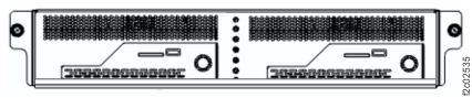
Locate the Ethernet switch SW1 (black network). Observe the power LED indicator. See Figure 20 and Figure 21.
Is the Ethernet switch powered on?- Yes, continue with the next step.
- No, go to MAP2350 Ethernet switch power problem.
Figure 20. Management enclosure locations (Model 983)
Figure 21. Ethernet switch, rear (Model 983)
-
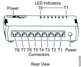
Observe the SW1 (Black network) Ethernet switch port LED for the failing management console
link.
See Table 5 and Figure 22 for a description of the Ethernet switch port LEDs.Is the port LED lit solidly or flashing?
- Yes, the Ethernet connection appears to be working. Go to step 13 to verify the connection.
- No, continue with the next step.
Table 5. Ethernet switch port LED description LED State Meaning Port LED Off No link On Link, No Activity Flashing Link, Activity Figure 22. Management enclosure Ethernet cables (Models 983)
-
Use Table 6 to locate both
ends of the Ethernet cable plugged into the Ethernet switch port with the LED indicator that is not
lit.
Table 6. Ethernet switch to management console cables Switch - port Management console - port (See Figure 23.) SW1-T7 MC1 - eth0 
SW1-T8 MC2 - eth0 
Figure 23. Model 98x management console cable connections (rear)
-
Is either end of the Ethernet cable unplugged?
- Yes, reconnect the cable and then go to step 13 to verify the repair.
- No, go to the next step.
- Unplug both ends of the suspect Ethernet cable.
- Temporarily connect the mid-length Ethernet cable FRU between the now empty connector ports.
- Is the Ethernet port LED lit solidly or flashing?
-
Replace the failing Ethernet cable.
- If the original Ethernet cable can be removed from the cable bundle, do that. If not, cut off both ends of the cable so it cannot accidentally be used.
- Route and connect the Ethernet cable FRU. Use hook-and-loop fasteners to secure the cable to the cable bundle.
- Go to step 13 to verify the fix.
-
Determine whether the Ethernet switch port is failing.
- Disconnect the Ethernet cable FRU from the Ethernet switch port.
- Temporarily disconnect the Ethernet cable from the Ethernet switch port 1. (It is not used.)
- Connect the Ethernet cable FRU to the Ethernet switch port T1.
- Is the Ethernet switch T1 port LED lit solidly or flashing?
-
Complete the following steps to replace the Ethernet switch.
- Remove the Ethernet cable FRU and return it to the FRU kit.
- Reconnect the original Ethernet cable to the Ethernet switch port 1.
- Reconnect the original Ethernet cable to the management console and Ethernet switch ports.
- Replace the Ethernet switch. Go to MAP7060 Replacing the Ethernet switch. Then, return here.
- Is the Ethernet switch port LED lit solidly or flashing?
-
Replace the management console.
- Replace the management console. Go to Exchange the small form factor management console. Then, return here.
-
Is the Ethernet switch port LED lit solidly or flashing?
- Yes, go to step 13 to verify the fix.
- No, contact your next level of support.
-
Verify the fix by using the Network Topology test tool as described in MAP7001 Using the network topology tool
Is the network problem resolved.- Yes, return to the serviceable event and close it by reviewing the steps in MAP1500 Ending a service action.
- No, contact your next level of support.