Exchange the disk drive module
Before you begin
 Use approved ESD procedures to prevent damage.
Attention:
- This procedure is not a stand-alone procedure. Customer disruption and damage to the hardware might occur when microcode and power boundaries are not in the proper conditions for this service action.
- If a serviceable event FRU repair directed you to this procedure, the microcode and power boundaries are already set.
- If a serviceable event FRU repair did not direct you to this procedure, see MAP1230 Replace a FRU without using a serviceable event.
Notes:
- All the cables and FRUs to be removed must be uniquely identified so they can be reinstalled correctly.
- If an installed earthquake resistance kit prevents you from accessing this FRU, refer to MAP1600.
Remove the disk drive module
About this task
Procedure
- Press the blue latch
 to release the Disk Drive Module (DDM)
handle. See Figure 1.
to release the Disk Drive Module (DDM)
handle. See Figure 1.
- Pull the handle
 out and to your left. This action
partly ejects the DDM out of its slot. See Figure 1.
out and to your left. This action
partly ejects the DDM out of its slot. See Figure 1.
Figure 1. Removing the disk drive module (16 DDM slot storage enclosure shown; 12 DDM slot storage enclosure DDM similar) 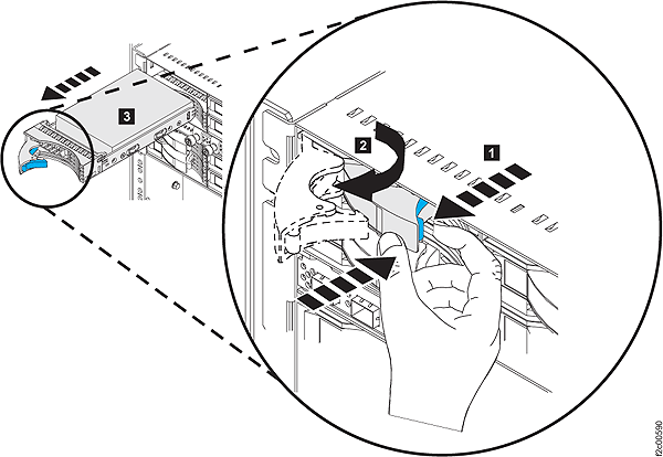
- Lift the DDM gently up as you pull it out of the
slot. This prevents any components on the bottom of the DDM from coming
in contact with the DDM or chassis surfaces below it. See Figure 2.
Figure 2. Disk Drive (angle to remove DDM) (16 DDM slot storage enclosure shown; 12 DDM slot storage enclosure DDM similar) 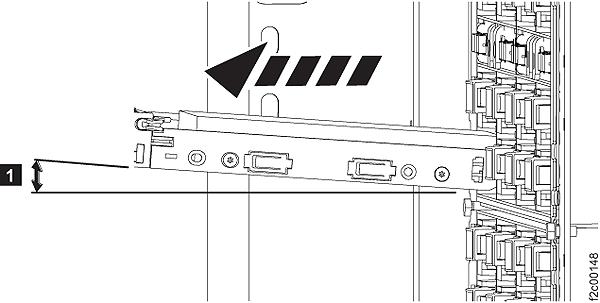
Install the disk drive module
About this task
Attention: If you bring a disk drive module
into the operating environment from an area that is outside the normal
operating temperature of 20 - 25 degrees C (66 - 77 degrees F), allow
the disk drive module time to acclimate to the operating environment.
Remove the disk drive module from any shipping package, leave the
disk drive module in the sealed plastic bag (if present) to prevent
condensation from forming.
Procedure
- Remove the factory-sealed wrapping from the new disk drive module only when you are ready to install it.
- Before installing the disk drive module, open the disk drive module handle by pressing the blue latch and pulling the handle open. See Figure 1.
- Hold the DDM at a slight up angle as you place it into the slot in the storage enclosure. Continue keep a gentle upward pressure as you slide it fully into the slot. The drive stops before it is fully seated. See Figure 2.
- Push the disk drive modules handle to the right until it is latched closed.
- Verify that the front of the new disk drive module is aligned with the other disk drive modules.
- Exit this service information center parts exchange procedure and return to the procedure that sent you here.