Exchange the Fibre Channel interface card (FCIC), optical
Before you begin
 Use approved ESD procedures to prevent damage.
Attention:
- This procedure is not a stand-alone procedure. Customer disruption and damage to the hardware might occur when microcode and power boundaries are not in the proper conditions for this service action.
- If a serviceable event FRU repair directed you to this procedure, the microcode and power boundaries are already set.
- If a serviceable event FRU repair did not direct you to this procedure, see MAP1230 Replace a FRU without using a serviceable event.
Notes:
- All the cables and FRUs to be removed must be uniquely identified so they can be reinstalled correctly.
- If an installed earthquake resistance kit prevents you from accessing this FRU, refer to MAP1600.
Remove Fibre Channel interface card (FCIC), optical
Procedure
- Are you replacing the left FCIC in the top storage
enclosure in a rack with overhead cable management (top exit) for
host and data cables?
- No, go to the next step.
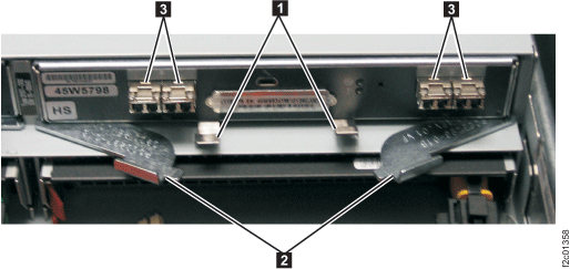
- Yes, you must remove the upper cable channel assembly
 . See Figure 1.
 - Loosen the retaining screw
 .
. - Pivot the upper cable channel assembly to the right and lift it out of the
tab slot
 .
.
- Loosen the retaining screw
Figure 1. Top tailgate upper cable channel assembly 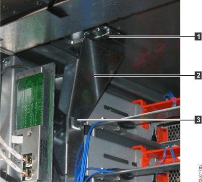
- To remove components from
the rear of the storage enclosure, you might need to:
- Loosen cable ties
- Remove the cable tray from the enclosure being serviced or the enclosure above it
- Loosen or release the cable ties holding the FC-AL and power cables as needed.
- If you need to remove the cable tray, release the cable ties. Then, lift up on the spring-loaded latches at the left and right end of the tray and then slide the tray to the rear. See Figure 2.
Figure 2. Cable tray spring-loaded latch 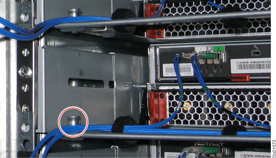
- At the rear of the rack, ensure that the FC-AL cables are properly labeled and disconnect
them from the small form-factor pluggables (SFPs) in the card being
removed. See Figure 3.
Note: An FC-AL cable that has been replaced will have no location label. Mark the cable so you can reconnect it to the same port later in this procedure.Attention: The FCIC card is pretested as an assembly. DO NOT remove or relocate SFPs from the card.
Figure 3. Storage enclosure FC-AL connections (rear) 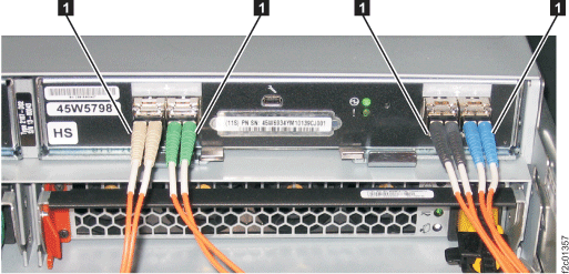
- Lift the retaining clips at the bottom center of the card,
and pull the card levers away from each other. This will eject
the card from its slot. See Figure 4.
- Gently pull the card from its slot using both hands. See Figure 4. Note: After the card is unplugged, storage enclosure fans may shift from low to high speed. This is normal behavior.
Figure 4. Removing the FCIC card