Exchange the PPS to rack operator panel UEPO cable and switch assembly

Before you begin

Icon for electrostatic discharge wrist strapUse approved ESD procedures to prevent damage.

Attention:
  • This procedure is not a stand-alone procedure. Customer disruption and damage to the hardware might occur when microcode and power boundaries are not in the proper conditions for this service action.
  • If a serviceable event FRU repair directed you to this procedure, the microcode and power boundaries are already set.
  • If a serviceable event FRU repair did not direct you to this procedure, see MAP1230 Replace a FRU without using a serviceable event.
Notes:
  • All the cables and FRUs to be removed must be uniquely identified so they can be reinstalled correctly.
  • If an installed earthquake resistance kit prevents you from accessing this FRU, refer to MAP1600.

Remove the PPS to rack operator panel UEPO cable and switch assembly

Procedure

  1. To locate this FRU, take one of the following actions and then return here and continue to replace the FRU:
    • If this FRU has a FRU identify indicator, use the FRU identify indicator, which is listed in MAP1240 Locating FRUs by using identify indicators. If not, use the location code.
      Note: There might be cases where the FRU failure or fencing conditions prevent the FRU LED indicator from being lit even if the FRU has power.
    • Use the location code, which is listed in MAP1245 Finding FRUs by using location codes.
    • If there is no FRU identify indicator or location code, you were sent here by an isolation MAP or symbolic FRU procedure. Use the information in that procedure and the figures in this procedure to locate the proper part to exchange.
  2. Most, but not all, FRUs have identify indicators. Use the flashing amber or solid blue FRU identify indicators to ensure that you are working on the correct enclosure or FRU.
  3. Ensure that all the racks in this storage facility are powered off.
  4. Log off and shutdown the management console (HMC).
  5. At the rear of each rack, switch off (down) the PPS-1 (upper) and PPS-2 (lower) power input circuit breakers.
  6. At the rear of both primary power supplies in each rack, unplug the cables from the sequencer module connector Callout label 16, squeeze the tab to release it.
    Figure 1. Rack power and cooling cables
    Rack power and cooling cables
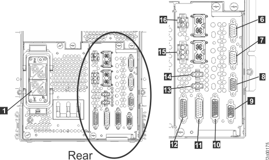
  7. At the front of the rack, remove the rack operator panel screws Callout label 1. See Figure 2.
    Figure 2. Rack operator panel UEPO switch assembly
    Rack operator panel UEPO switch cables
  8. Remove the UEPO switch/cable assembly from the bracket.
  9. Remove the cable retention hardware as needed and then remove the cable and switch assembly.

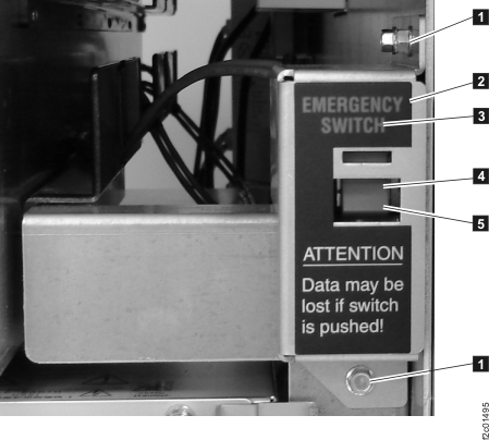
Install the PPS to rack operator panel UEPO cable and switch assembly

Procedure

  1. Route the new cable and switch assembly.
  2. Observe the "top" label on the UEPO switch and ensure it is facing up.
  3. Connect a cable to connector J16 of each PPS.
  4. Install the cable retention hardware.
  5. Switch on (up) the input circuit breakers on both PPSs.
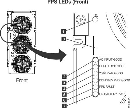
  6. At the front of each PPS, ensure the UEPO LOOP GOOD indicator Callout label 3 in Figure 3 is lit.
    Note: If the indicator on both PPSs are not lit, then the switch might be installed upside down. If the indicator is not lit on one PPS only, isolate the problem before continuing.
    Figure 3. LEDs on the PPS (front)
    LEDs on the PPS (front)
  7. Wait for the management console green LED power indicator to slow blink, then switch on the management console.
  8. Power on the storage facility using the normal management console Power Control Modes menu options. Refer to MAP1211 Controlling the storage facility power from the management console.
  9. Exit this service information center parts exchange procedure and return to the procedure that sent you here.