Exchange the rack identity card to operator panel cable/LED assembly
Before you begin
 Use approved ESD procedures to prevent damage.
Attention:
- This procedure is not a stand-alone procedure. Customer disruption and damage to the hardware might occur when microcode and power boundaries are not in the proper conditions for this service action.
- If a serviceable event FRU repair directed you to this procedure, the microcode and power boundaries are already set.
- If a serviceable event FRU repair did not direct you to this procedure, see MAP1230 Replace a FRU without using a serviceable event.
Notes:
- All the cables and FRUs to be removed must be uniquely identified so they can be reinstalled correctly.
- If an installed earthquake resistance kit prevents you from accessing this FRU, refer to MAP1600.
Remove rack identity card to operator panel cable/LED assembly
Procedure
- To disconnect the cable at the rack identity card
 , squeeze the tab to release it.
 Figure 1. Rack power and cooling local remote and rack identity card cables 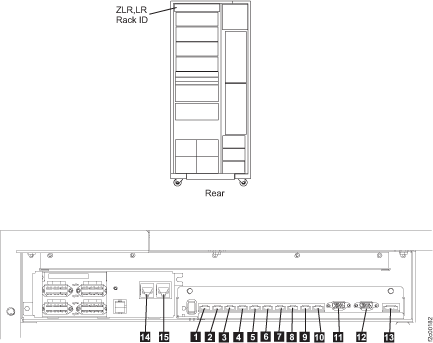
- At the front of the rack, remove the two rack operator
panel screws
 . See Figure 2.
Figure 2. Rack operator panel LED assembly 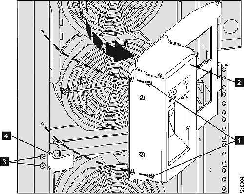
- To disconnect the cable at the operator panel, squeeze the tab
to release it.
Figure 3. Rack operator panel UEPO switch cables 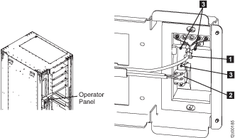
Install rack identity card to operator panel cable/LED assembly
Procedure
- Route the cable.
- Connect the cable to the rack identity card connector . See Figure 1.
- Connect the cable to the operator panel connector. See Figure 3.
- Ensure there is enough cable free play when the operator panel is in the full open position.
- Install the cable retention hardware.
- Exit this service information center parts exchange procedure and return to the procedure that sent you here.