Exchange the RPC card to rack identity card cable
Before you begin
 Use approved ESD procedures to prevent damage.
Attention:
- This procedure is not a stand-alone procedure. Customer disruption and damage to the hardware might occur when microcode and power boundaries are not in the proper conditions for this service action.
- If a serviceable event FRU repair directed you to this procedure, the microcode and power boundaries are already set.
- If a serviceable event FRU repair did not direct you to this procedure, see MAP1230 Replace a FRU without using a serviceable event.
Notes:
- All the cables and FRUs to be removed must be uniquely identified so they can be reinstalled correctly.
- If an installed earthquake resistance kit prevents you from accessing this FRU, refer to MAP1600.
Remove RPC card to rack identity card cable
Procedure
- Disconnect the cable at the RPC card connector (Cx-J1).
See Figure 1.
Figure 1. Location codes for the RPC card (Model 98x) 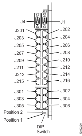
- Disconnect the cable at the rack identity card connector
 or
or  . See Table 1 and Figure 2.
Table 1. RPC to rack identity card cables From RPC port RPC card (facing rear) To rack identity card connector C1-J1 Left C5-J1 C2-J1 Right C5-J2 Figure 2. Location codes for the rack identity card 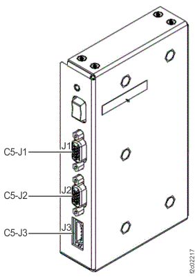
Install RPC card to rack identity card cable
Procedure
- Route the cable.
- Connect the cable to the RPC card connector.
- Connect the cable to the rack identity card connector.
- Install the cable retention hardware.
- Exit this service information center parts exchange procedure and return to the procedure that sent you here.