Exchange the laptop unit (T520, T530, T540)

Before you begin

Icon for electrostatic discharge wrist strapUse approved ESD procedures to prevent damage.

Attention:
  • This procedure is not a stand-alone procedure. Customer disruption and damage to the hardware might occur when microcode and power boundaries are not in the proper conditions for this service action.
  • If a serviceable event FRU repair directed you to this procedure, the microcode and power boundaries are already set.
  • If a serviceable event FRU repair did not direct you to this procedure, see MAP1230 Replace a FRU without using a serviceable event.
Notes:
  • All the cables and FRUs to be removed must be uniquely identified so they can be reinstalled correctly.
  • If an installed earthquake resistance kit prevents you from accessing this FRU, refer to MAP1600.

Remove the laptop unit

Procedure

  1. If this storage facility does not have a second laptop unit connected and functioning, the customer will not have access to manage their storage while you perform this procedure. Ensure that they are aware of this.
  2. Shut down the laptop unit. See MAP6640 Shutting down, restarting, and logging off the management console for more information.
  3. At the laptop unit, disconnect the power and communication cables.
    1. For T520 and T530 management consoles, disconnect the following (see Figure 1):
      • Power Callout label 5
      • Left side, upper USB for eth0 black private network Callout label 1
      • Left side, lower USB for eth3 gray private network Callout label 2
      • Rear USB for modem Callout label 3
      • eth2 customer network Callout label 4
    2. For T540 management consoles, disconnect the following (see Figure 2 and Figure 3):
      • Power Callout label 2 Figure 2
      • Power-on card power near Callout label 2 Figure 2
      • Left side, front USB for eth0 black private network Callout label 7 Figure 2
      • Left side, rear USB for eth3 gray private network Callout label 6 Figure 2
      • Right side, rear USB for modem Callout label 6 Figure 3
      • eth2 customer network Callout label 1 Figure 2
    Figure 1. ThinkPad T520, T530 laptop unit cable connections
    ThinkPad T520 laptop unit cable connections
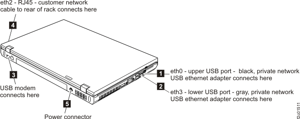
    Figure 2. ThinkPad T540 laptop unit cable connections (left and rear)
    ThinkPad T540 laptop unit cable connections (left and rear)
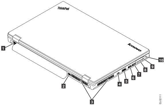
    Figure 3. ThinkPad T540 laptop unit cable connections (right)
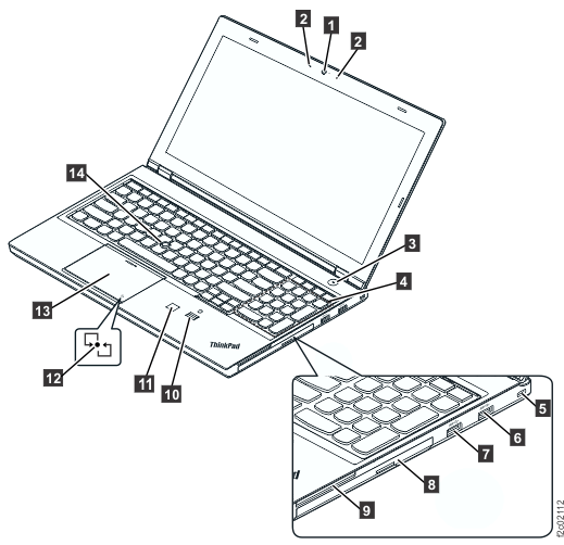
    ThinkPad T540 laptop unit cable connections (right)
  4. Lift the laptop unit up from the rectangular tray assembly. The laptop is held to the tray assembly with patches of cable ties.
  5. If the laptop automatic power-on card is being replaced, it can be removed from the docking connector on the bottom of the laptop.

Install the laptop unit

Procedure

  1. If the laptop is being replaced, move parts from the old laptop to the new laptop.
    1. The hard drive, DVD-RAM drive, and memory DIMM from the old laptop unit need to be moved to the new laptop unit. The new laptop FRU typically will not include these. The old hard drive already has working and configured code.
    2. If the laptop being replaced contains an SDHC memory card in the media card reader slot (Callout label 1, Figure 4 or Callout label 7, Figure 5), it must be moved to the new laptop unit.
    3. Reference the IBM® DS8000® series Service Documents CDROM that came with the installation shipment group. It should be stored in the front upper left open compartment of Rack-1. Start the CD and open the laptop unit service documentation PDF.
    Figure 4. Management console media slots (T520, T530)
    Management console media slots
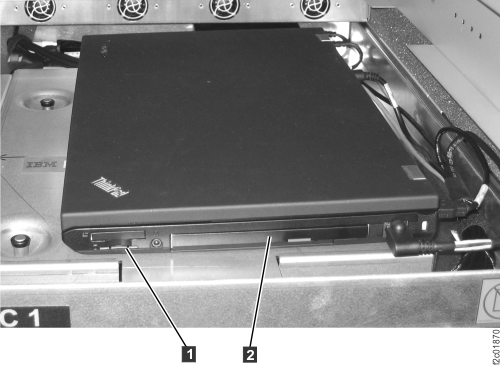
    Figure 5. Management console left side view (T540)
    Management console left side view (T540)
  2. If the laptop is being replaced, the new laptop unit needs the cable ties strips installed on the bottom.
    1. The laptop unit FRU kit includes cable ties material.
    2. Reference the old laptop and apply the cable ties to the new laptop in the same locations.
  3. If the automatic power-on card was removed, reinstall it now.
  4. Physically install the new laptop unit in the rack, and ensure all cables are properly connected, as shown in Figure 1 or Figure 2 and Figure 3.
  5. Power the laptop unit on and wait for the login screen. Does the login screen display?
  6. Test the laptop unit to ensure all connections are functioning:
    1. Use the network topology tool to ensure the gray and black private network connections are functioning. See MAP7001 Using the network topology tool for more information.
    2. Display open serviceable events needing repair. If there are serviceable events related to this HMC or private network timeout problems created before or during the time you replaced this laptop unit, close them now.
    3. Run the storage facility status (end of call) option. See MAP1100 View storage facility state (end of call) for more information.
    4. If the customer allows a phone line connection, test the modem. Select Service Management > Manage Outbound Connectivity > Configure > Local Modem > Test.
    5. If the customer allows VPN connections, test it. Select Service Management > Manage Outbound Connectivity > Internet VPN > Test . If the test fails, see MAP1301 Isolating Call Home/remote services failure.
    6. Ask the customer to test the access of the application or method that they will use to connect to the DS8000 Storage Manager in the laptop unit.