Exchange the CEC enclosure I2C interface card assembly
Before you begin
 Use approved ESD procedures to prevent damage.
Attention:
- This procedure is not a stand-alone procedure. Customer disruption and damage to the hardware might occur when microcode and power boundaries are not in the proper conditions for this service action.
- If a serviceable event FRU repair directed you to this procedure, the microcode and power boundaries are already set.
- If a serviceable event FRU repair did not direct you to this procedure, see MAP1230 Replace a FRU without using a serviceable event.
Notes:
- All the cables and FRUs to be removed must be uniquely identified so they can be reinstalled correctly.
- If an installed earthquake resistance kit prevents you from accessing this FRU, refer to MAP1600.
Remove the CEC enclosure I2C interface card assembly
About this task
Note: The CEC enclosure I2C interface card assembly FRU is
a kit that contains the following two pieces:
- I2C interface card with five cables permanently attached. This card is located at the front of the CEC enclosure.
- I2C passive connector card which is a cable interposer between the internal ribbon cable and the external RJ-45 cable.
Procedure
- Move the management console laptop
from the service position
 to the DC-UPS service position
  , as shown in Figure 1. Refer to Management console service positions (Model 961).
 Figure 1. Alternate service position 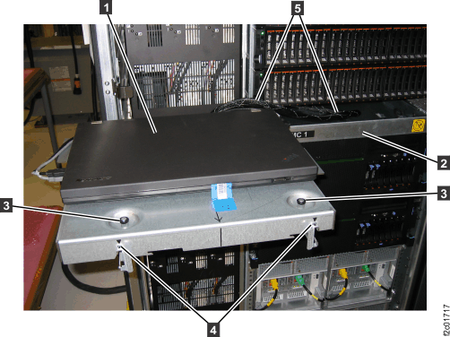
- Push the now empty management console
tray fully into the rack. See Figure 1. This allows
access to the top and rear of the CEC enclosure.
- Use the CEC enclosure front and rear
blue identify LEDs to determine the CEC enclosure to be repaired.
Both blue LEDs should be solidly lit.
- CEC control panel blue identify LED
 , as shown in Figure 2
 - CEC enclosure rear blue identify LED
 , as shown in Figure 3
Note: If both the front and rear CEC enclosure identify LEDs are not lit, use the location code listed in the serviceable event FRU list. See MAP1245 Finding FRUs by using location codes.Figure 2. CEC enclosure control panel assembly (Model 961) 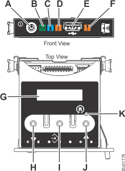
Figure 3. CEC enclosure rear LED indicators 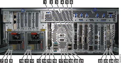
- CEC control panel blue identify LED
- Verify the CEC enclosure is in the
power-off state. See Figure 4.
- At the rear of the CEC enclosure, view both CEC enclosure power supply DC GOOD LEDs.
- Are both DC GOOD (output) LEDs blinking?
- Yes, continue with the next step.
- No, do not continue with this FRU replacement. Go to MAP4841 CEC enclosure fails to power off during service processor repair (Models 961, 98x).
Figure 4. CEC enclosure power supply LEDs (Model 961) 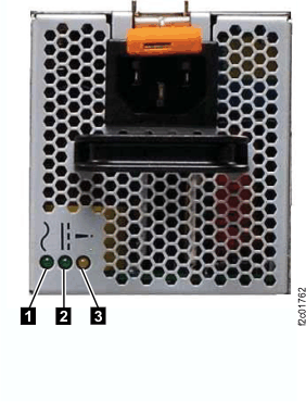
- Disconnect the power cables (E1-J1 and
E2-J1) from the CEC with the DC Good LEDs blinking. See Figure 5. Note: The CEC enclosure power supply LEDs continue to blink for up to 20 seconds while internal power is discharged.
- Each power cable is looped once around the CEC enclosure power supply handle and secured with a cable tie.
- Remove the cable tie, unplug the cable and unwrap it from the handle.
Figure 5. Location codes for the CEC enclosure (rear view) (Model 961) 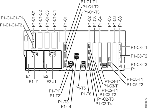
- Observe the CEC enclosure control panel
green power present icon
 . See Figure 6.
- If it is off, go to the next step.
- If it is slow blinking, the CEC enclosure is still in the power-off state. DO NOT CONTINUE. Ensure that you have unplugged the power cables.
Figure 6. CEC enclosure control panel 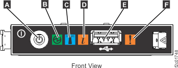
- At the front of the CEC enclosure,
remove the two screws
 (if present) that secure the CEC enclosure to the rack. See Figure 7.
 Figure 7. Preparing the CEC enclosure for service position 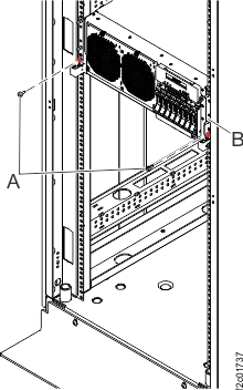
- Pull the CEC enclosure fully out
to the service position.
- Hold the CEC enclosure release latches down on both the left and right sides,
and pull the CEC enclosure full out. See Figure 8.
- Ensure both slide rails both latch in the full out position.
Figure 8. Pulling the CEC enclosure out to the service position 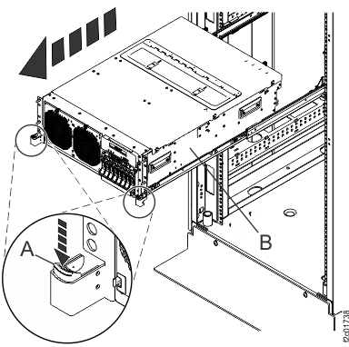
- Hold the CEC enclosure release latches
- Remove the CEC enclosure front cover.
See Figure 9.
Figure 9. Removing the CEC enclosure front cover 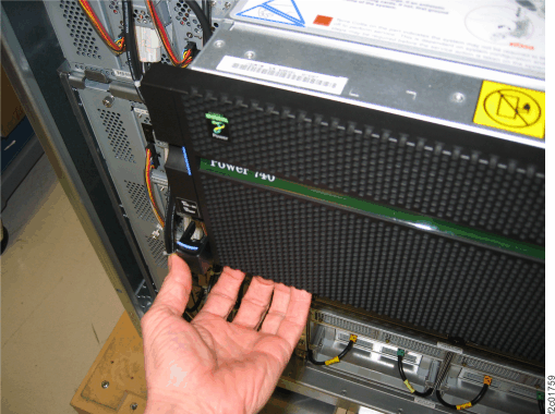
- Remove the CEC enclosure service
access cover. See Figure 10.
- Loosen the two thumbscrews located at the back of the cover.
- Slide the cover toward the back of the CEC enclosure. When the front of the service access cover has cleared the upper frame ledge, lift the cover up and off the CEC enclosure.
Figure 10. Removing the service access cover 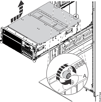
- Loosen the two thumbscrews
- Remove the ribbon cable from the I2C passive
connector card . See Figure 11. Release the ribbon
cable fully from the card connector and
from the vertical retention slot
 .
. Figure 11. Removing the I2C passive connector card 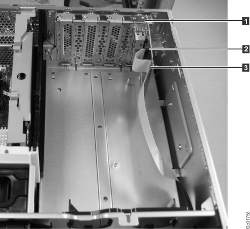
- Remove the control panel. See Figure 12.
- Press the blue release tab to the left and pull the control panel out to the service position.
- Remove the control panel by pressing the locking tabs located on either side of the panel,
grasping the edges of the panel, and pulling the panel out of its
bay.
- Disconnect the control-panel signal cable and its related USB cable from the back of the control
panel.
Figure 12. Removing the control panel 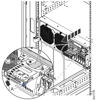
- Remove the I2C interface card (P1-C19).
- The I2C interface card is to the right of the memory cards.
See Figure 13.
Figure 13. Removing the I2C interface card 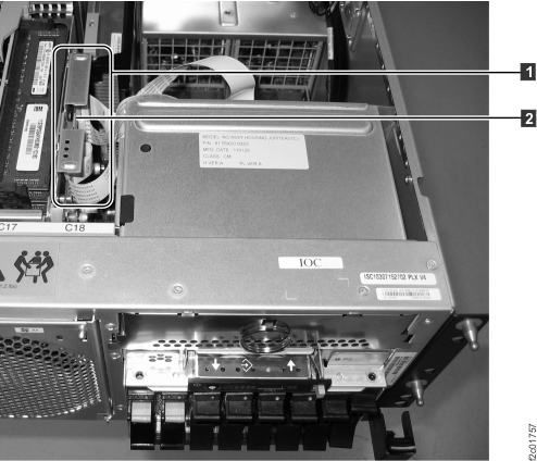
- The I2C interface card has five cable ends. See Figure 14. Trace
each cable to its destination and disconnect it from that connector.
- control panel USB and , control panel signal cables were
already disconnected in a prior step.
 , was already released from I2C passive
card in a prior step.
, was already released from I2C passive
card in a prior step. , release it from the system backplane.
See Figure 15,
Control Panel Signal.
, release it from the system backplane.
See Figure 15,
Control Panel Signal.- , release it from the system backplane.
See Figure 15,
Control Panel USB.
Figure 14. I2C interface card cables 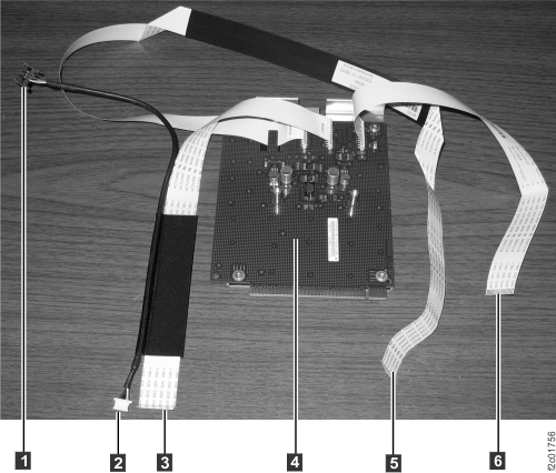
Figure 15. Disconnecting the internal cables 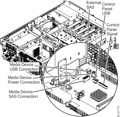
- Press the blue release latch and lift the card out of the slot.
See Figure 13.
- The I2C interface card
Install the CEC enclosure I2C interface card assembly
Procedure
- Install the I2C interface card (P1-C19).
- Install the card into it's slot. Push down until the
blue latch snaps into place. See Figure 13.
- Route the control panel cable bundle through the control panel opening
so that the cables connectors stick out the front of the CEC enclosure.
See Figure 14.
- Connect the control panel USB cable Figure 14 to
the system backplane (Figure 15).
- Connect the control panel signal cable Figure 14 to
the control panel USB connector (Figure 15) on
the system backplane.
- Route the I2C cable Figure 14 to
the I2C passive card location at the right rear of the CEC enclosure
(Figure 11).
- Install the card
- Install the I2C passive connector
card. See Figure 11.
- Insert the ribbon cable into the card connector . Ensure the cable passes through the
two vertical slots in the card.
- Install the card into the slot.
- Insert the ribbon cable
- Install the control panel. See Figure 12.
- Connect the control-panel signal cable and its related USB cable to the rear of the control panel.
- Install the control panel assembly by sliding it into
the CEC enclosure until the locking tabs located on either side of the panel
snap into place.
- Slide the control panel fully into the CEC enclosure until the blue latch snaps into place.
- Connect the control-panel signal cable
- Install the service access cover.
See Figure 10.
- Place the service access cover on top of the system, about 25 mm (1 in.) from the upper chassis ledge.
- Hold the service access cover against the system unit and slide it toward the front of the system. The tabs of the service access cover slide beneath the upper chassis ledge.
- Align the two thumbscrews located on the back of the service
access cover with the two holes on the back of the system chassis.
- Tighten the thumbscrews to secure the service access cover.
- Connect the power cables (E1-J1, E2-J1)
to both CEC enclosure power supplies. See Figure 4.
- Loop the power cable around the power supply handle and connect it.
- Secure the cable with the cable tie.
Is the DC Good green LED blinking on one or both power supplies?
- Yes, go to the next step.
- No, ensure the power cables are properly connected. If no cable problem is found, call the next level of support.
Figure 16. CEC enclosure power supply cable loops 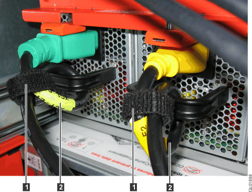
- Return the management console
laptop to the standard service position on the slide-out tray. See Figure 1.
- Slide the empty management console tray out to the service position.
- Move the laptop assembly from the DC-UPS service position to the standard service position . Carefully route the cable bundle.
- Push the DC-UPS service position rails fully in.
- Slide the empty management console tray