MAP2220 CEC enclosure to RPC card I2C communication failure
A view of the detail data for one of the RPCs interrupt
registers is not available from one or both clusters.
About this task
Only the base LPAR in a CEC enclosure communicates with the RPC cards. The LPAR
communicates with the service processor through the RTAS
interface. The service processor communicates with both
RPC cards through a shared I2C interface. The same I2C interface also communicates with the CEC
enclosure control panel.
MAP2220 Section-1
Procedure
Display open serviceable events. Find those with the SRCs listed in Table 1. Use Table 1 to prioritize the
order of repair.
Table 1. SRC and associated actions
SRC repair order
SRC definition1, 2
Go to
BE190010
CEC enclosure 1 failed to communicate with RPC1 and RPC2.
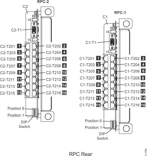
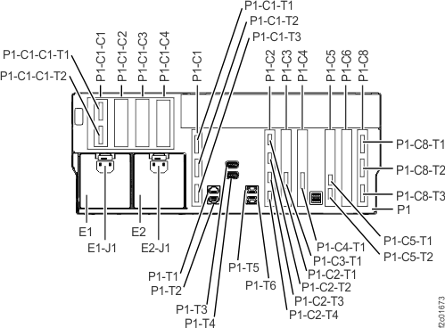
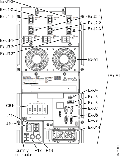
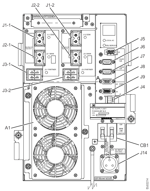
Figure 1. Location codes
for the RPC cards (Models 941, 951)
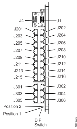
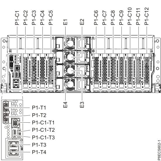
Figure 2. Location codes for the RPC cards (Model 961)
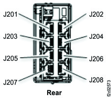
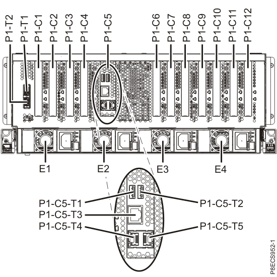
Figure 3. Location codes for the RPC card (Model 98x)
Figure 4. Location codes for the RPC card (Model 983), rear of management enclosureFigure 5. Location codes for the CEC enclosure (rear view) (Models 941, 951)
Figure 6. Location codes for the CEC enclosure (rear view) (Model 961)
Figure 7. Location codes for the CEC enclosure (rear view) (Models 980, 981, 984, 985, and 986)
Note: Models 981, 985, and
986 CEC are shown; model
980, 983, 984 card
locations are similar.
Figure 8. CEC enclosure location codes (rear view) (Model 982 and
988)Figure 9. Location
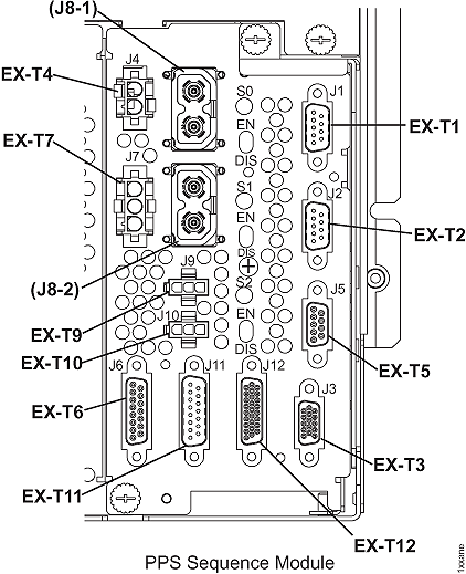
codes for the PPS sequencer module
Figure 10. Location codes for the DC-UPS (Models 961, 96E, 98x
three-phase) (rear)Figure 11. Location codes for the DC-UPS (Models 98x,
single-phase) (rear)
MAP2220 Section-2 (One CEC communication failure with both
RPC cards)
About this task
One CEC enclosure has a communication
failure through its service processor to both RPC cards.
Procedure
Use
the SRC in the serviceable event that sent you here and refer to Table 2 for an overall description
of your failure. The failure could be caused by one
of the following FRUs, which are listed in alphabetical order:
Models 941, 951:
CEC enclosure control panel
CEC enclosure service processor
CEC enclosure I/O backplane assembly
RPC card
RPC card to CEC enclosure cable (I2C Y-Cable)
Model 961:
CEC enclosure control panel
CEC enclosure system
backplane (Model 961) (contains service processor function)
CEC enclosure I2C card
RPC card to CEC enclosure I2C cable
RPC card
Models 980, 981, 983, 984, 985,
986:
CEC enclosure control panel
CEC enclosure system backplane (contains service processor
function)
CEC enclosure I2C card
RPC card to CEC enclosure I2C cable
RPC card
Models 982, 988:
CEC enclosure control panel
CEC enclosure service processor card
CEC enclosure I2C card
RPC card to CEC enclosure I2C cable
RPC card
Table 2. SRC communication-failure resources
SRC
Communication failure resources
BE190010
CEC enclosure 1 failure
to communicate with RPC1 card and RPC2 card
BE190011
CEC enclosure 2 failure
to communicate with RPC1 card and RPC2 card
Display open serviceable events that need repair. Is there any other serviceable event with FRUs listed in step 1?
Yes, exit this MAP and attempt to repair that serviceable event first. If that repair does not correct this
problem, return here and continue with the next step. If that repair does correct this problem,
remember to also close this serviceable event.
No, go to the next step.
Observe the CEC enclosure control
panel. Does the control panel display a ball icon slowly moving clockwise
around the display?
MAP2220 Section-3 (Both CECs communication failure with one
RPC card)
About this task
Both CEC enclosures have a communication failure through their service processor to the same RPC card. The working RPC card is not reporting any problem with the
suspect RPC card. There should be no single point
of failure that can cause this failure condition.
Procedure
Use the SRC in the serviceable event that
sent you here to determine which RPC card the CEC failed to communicate
with. Refer to Table 3.
Table 3. SRC communication interface-failure
resources
SRC
Communication failure resources
BE190012
Both CEC enclosureservice processors, failure to communicate
with RPC1 card
Models 941, 951, see Figure 1 (RPC1 is on the right, viewed from rear).
Model 98x (not 983)
see Figure 3. (RPC2 is on the right, viewed from rear)
Model 983 see Figure 4. (RPC2 is on the right, viewed from rear)
Display serviceable
events that need repair. Is
there any other serviceable event listing the RPC card
determined in step 1 or CEC enclosure to RPC card cable
that connects to it?
Yes, exit this MAP and attempt to repair that serviceable event first. If that repair does not correct this
problem also, return here and continue at the next step. If that repair does not correct this
problem, remember to also close this serviceable event.
No, go to the next step.
At the suspect RPC card determined
in step 1, ensure all
the cables are properly connected before you continue. If any cables
are not connected, do not connect them now. Instead go to the next
step and do a psuedo repair of the RPC card. When you are directed
to replace the RPC card, do not replace it but instead connect the
cables.
The possible failing FRUs are the RPC card and
CEC enclosure to RPC card cable.
Use the Exchange Parts procedure to select the suspect
RPC card determined in step 1:
From the navigation area, click Storage
Facility Management > storage facility.
From the bottom Task area, click Exchange
Parts > Exchange Rack Components .... The Show Rack Enclosures window opens.
Select a rack and click Show FRUs. The
Show Rack FRUs window opens.
Select the suspect RPC Card FRU and continue the guided
repair.
From the Show Rack FRUs window, select RPC Card and
click Exchange FRU.
MAP2220 Section-4
Procedure
The CEC enclosure control
panel displays this clockwise moving icon when:
The control panel was installed into the CEC enclosure and the
service processor firmware has not logically installed the control
panel, see step 2.
The control panel is failing and needs to be replaced.
The default setting for the control panel is "installed." If the setting
is "not installed" and the control panel is installed in the CEC enclosure with CEC power on, the
icon moves slowly clockwise around the display. Use the ASMI Concurrent
Maintenance > Control Panel menu option to ensure the control panel is
logically installed. Refer to the MAP1221 ASMI menu structure.
If the control panel itself is failing, replace the control
panel. Refer to MAP1215 Replace a FRU.
MAP2220 Section-5 (One CEC
communication failure to both RPC cards, continued)
Procedure
Determine whether the CEC enclosure to RPC card cable is causing the problem.
If an RPC card is listed in the serviceable event
FRU list, then it is fenced.
If an RPC card is not listed in the serviceable event FRU list, use MAP1100 View storage facility state (end of call) to display fenced resources and then
click Details to determine which RPC is fenced.
If no RPC shows as fenced, check for codes XE or XF on the status
display of both DC-UPSs. Use Table 9 to select which RPC card
to use for the next step.
Note: Any combination of codes may be displayed. You are only concerned
with XE and XF.
Table 9. RPC card to pseudo-repair when none are fenced
DC-UPS status display
RPC card to pseudo-repair in next step
Both DC-UPSs show XF
RPC2 card (R1-C2)
Both DC-UPSs show XE
RPC1 card (R1-C1)
Any other condition, including: XE on one DC-UPS (but not
both) XF on one DC-UPS (but not both)
RPC1 card (R1-C1)
Do a pseudo repair of the fenced RPC card.
This resets the existing RPC card without
replacing it.
Important: The CEC enclosure must not be
power cycled or rebooted while the control panel is removed, to ensure that the load of the
functional code succeeds.
Do a pseudo repair of the fenced RPC card.
This resets the existing RPC card without
replacing it.
RPC1 card (only when it is fenced; use MAP1100 to display fenced resources)
RPC2 card (only when it is fenced; use MAP1100 to display fenced resources)
Model 961:
CEC enclosure system backplane (Model 961) (contains service processor function)
CEC enclosure I2C card
RPC card to CEC enclosure I2C cable
RPC1 card (only when it is fenced; use MAP1100 to display fenced resources)
RPC2 card (only when it is fenced; use MAP1100 to display fenced resources)
Models 980, 981, 983, 984,
985, 986:
CEC enclosure system backplane (Model 98x) (contains service processor function)
CEC enclosure I2C card
RPC card to CEC enclosure I2C cable
RPC1 card (only when it is fenced; use MAP1100 to display fenced resources)
RPC2 card (only when it is fenced; use MAP1100 to display fenced resources)
Models 982, 988:
CEC enclosure service processor card
CEC enclosure I2C card
RPC card to CEC enclosure I2C cable
RPC1 card (only when it is fenced; use MAP1100 to display fenced resources)
RPC2 card (only when it is fenced; use MAP1100 to display fenced resources)
MAP2220 Section-6 (One CEC communication failure with one RPC
card)
About this task
One CEC enclosure has a communication failure through the service processor to one RPC card. The RPC card is not reporting any communication failures
to the service processor.
Use the SRC in the
serviceable event that sent you here to determine the failing communication
interface. For Models 941, 951, use Table 10. For Model 961,
use Table 11. For Model 98x, use Table 12.
Models 941, 951:
Inspect the RPC card to CEC enclosure cable (I2C Y-Cable) for
damage or misplugging. Ensure it is fully seated by pressing on each
connector.
If a problem is found, the cable can be hot-plugged.
Most likely one of the RPC cards is fenced. Before this service
action is complete, if that RPC card is not replaced for another reason,
then that RPC card needs to go through a pseudo repair. A pseudo repair
means the parts exchange process for that RPC card is used to create
a reset to that card without physically replacing that RPC card. MAP1100 Section-27, Fenced Resources can
be used to display fenced resources.
Continue at the next step.
Table 10. SRC communication
interface-failure resources (Models 941, 951)
SRC
Communication failure resources
Y-Cable Connections for this SRC
BE190014
CEC enclosure 1 (upper), failure to communicate
with RPC1 card (right viewed from rear)
CEC enclosure 2 (lower), failure to communicate
with RPC2 card (left viewed from rear)
Model 961:
Inspect the RPC card to CEC enclosure cable for damage or misplugging.
Ensure it is fully seated by pressing on each connector.
If a problem is found, the cable can be hot-plugged.
Most likely one of the RPC cards is fenced. Before this service
action is complete, if that RPC card is not replaced for another reason,
then that RPC card needs to go through a pseudo repair. A pseudo repair
means the parts exchange process for that RPC card is used to create
a reset to that card without physically replacing that RPC card. MAP1100 Section-27, Fenced Resources can
be used to display fenced resources.
Continue at the next step.
Table 11. SRC communication
interface-failure resources (Model 961)
SRC
Communication failure resources
Y-Cable Connections for this SRC
BE190014
CEC enclosure 1 (upper), failure to communicate
with RPC1 card (upper)
Inspect the RPC card to CEC enclosure cable for damage or misplugging.
Ensure it is fully seated by pressing on each connector.
If a problem is found, the cable can be hot-plugged.
Most likely one of the RPC cards is fenced. Before this service
action is complete, if that RPC card is not replaced for another reason,
then that RPC card needs to go through a pseudo repair. A pseudo repair
means the parts exchange process for that RPC card is used to create
a reset to that card without physically replacing that RPC card. MAP1100 Section-27, Fenced Resources can
be used to display fenced resources.
Continue at the next step.
Table 12. SRC communication interface-failure resources (Model 98x)
SRC
Communication failure resources
Y-Cable Connections for this SRC
BE190014
CEC enclosure 1 (upper), failure to communicate
with RPC1 card (left)