MAP2740 Power distribution unit (PDU) isolation (Models 98x)
MAP2740 Section-1
Procedure
-
At the rear of the rack with the failure, locate the four PDUs (E21 - E24). Refer to the
location codes in the serviceable event FRU list to determine the rack with the failure.
Figure 1 shows Rack-1; racks 2, 3, 4, and 5 are similar.
Figure 1. Model 98x base rack locations. Note: Models 980, 981, and 982 are shown. PDU locations are similar for models 984, 985, 986, and 988.
- On each PDU, locate the two sets of output power LEDs.
One set is for the upper connectors J1-J6, the other set is for the
lower connectors J7-J12 (Figure 2).
- The upper six output connectors (J1-J6) share power from input cable P1.
- The lower six output connectors (J7-J12) share power from input cable P2.
- Each output power connector is protected by an internal fuse that is not repairable.
- Each output power connector has an associated green LED that is lit when the fuse is good and output power is present.
Figure 2. Locations for power distribution unit (PDU) connectors  Attention: If you are here for a high-performance flash enclosure problem that occurred while installing that enclosure (as part of a flash enclosure MES or an expansion rack installation), you analyze and repair the problem by finding the condition that applies in Table 1. Later, you use MAP2740 Section-5 PDU and power supply isolation during flash enclosure installation to complete the repair.
MAP2740 Section-2 PDU LEDs J1-J6 or J7-J12, one LED is not lit
About this task
Procedure
MAP2740 Section-3 PDU LEDs J1-J6 or J7-J12, six LEDs are not lit
About this task
Procedure
-
At the top of the DSU, observe the:
- For single-phase:
- For three-phase:
Are all four LEDs on the single-phase DSU or all six LEDs on the three-phase DSU lit?
Figure 3. LEDs on the DC-UPS DC Supply Unit (DSU) (Models 98x, single-phase power) (rear) 
Figure 4. LEDs on the DC-UPS DC Supply Unit (DSU) (Models 98x, three-phase power) (rear) 
 for connectors J2-1, J2-2. See
 MAP2740 Section-4 PDU LEDs J1-J12 are all lit
Procedure
MAP2740 Section-5 PDU and power supply isolation during flash enclosure installation
About this task
Procedure
MAP2740 Section-6 Enclosure power input problem (Model 983)
About this task
You are using MAP2740 Power distribution unit (PDU) isolation (Models 98x) to isolate power input problem to a CEC enclosure, I/O enclosure (2U), or storage enclosure (24 drive slots).
Procedure
MAP2740 Section-7 CEC enclosure power input problem (Model 983)
Procedure
-
Locate the CEC enclosure power supply by using the location code from the serviceable event FRU
list that sent you here. See Figure 5.
Figure 5. Location codes for CEC enclosure (rear view) (Models 983) 
-
Observe the failing CEC enclosure power supply LEDs. See Figure 6.
Is the AC input green LED lit?- Yes. The failure is in the CEC enclosure. Exit this MAP and replace the next FRU in the FRU list.
- No. Go to step 3.
Figure 6. Location of the CEC enclosure power supplies and LEDs (Model 983) 
-
Is the power cable connected and fully seated at the CEC enclosure power supply and UPS? See
Table 2, Figure 6, Figure 7, and Figure 8.
- Yes. Go to step 4.
- No. Exit this MAP and select the power supply in the FRU list. When directed to replace it, correct the power cable problem.
Table 2. CEC enclosure power cables from UPS CEC enclosure CEC enclosure power input connector UPS UPS power output connector XC1 (upper) E1 (green) E61 (upper) J6 (green) XC1 (upper) E2 (yellow) E62 (lower) J6 (yellow) XC2 (lower) E1 (green) E61 (upper) J7 (green) XC2 (lower) E2 (yellow) E62 (lower) J7 (yellow) Figure 7. UPS output power cables to enclosures (rear) 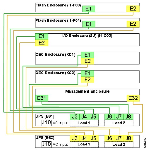
Figure 8. Location codes for the UPS (Model 983), rear view 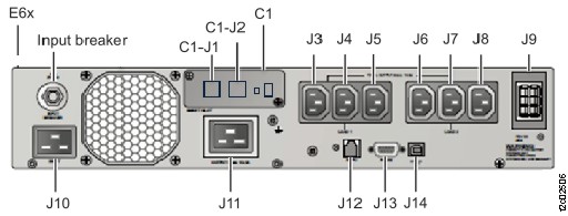
MAP2740 Section-8 I/O enclosure (2U) power input problem (Model 983)
Procedure
-
Locate the I/O enclosure (2U) power supply using the location code from the serviceable event
FRU list that sent you here. See Figure 9.
Figure 9. Location codes for I/O enclosure (2U) (rear view) (Models 983) 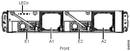
-
Observe the failing I/O enclosure power supply LEDs. See Figure 10.
Is the power input green LED lit?
lit?
- Yes. The failure is in the I/O enclosure. Exit this MAP and replace the next FRU in the FRU list.
- No. Go to step 3.
Note: The next step checks the power cables between the UPS output connector and the I/O enclosure power supply input connector.- The power cable from the UPS connects to the rear left of the I/O enclosure. The cables and connectors are color coded.
- There are two permanently installed power cables inside the enclosure going from the rear connectors to the power supply connectors at the front of the enclosure. To replace an internal power cable, the entire sheet metal enclosure must be replaced. The enclosure contains two power cables and also the front LED indicator cable assembly. The customer will not have access to their data during the FRU replace.
Figure 10. Location of the I/O enclosure power supply LEDs (Model 983) 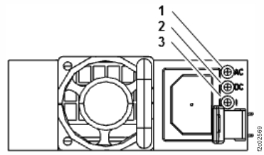
-
Ensure the three cable connections are connected and fully seated. See Table 3.
- Cable connection at enclosure power supply (front). See Figure 9.
- Cable connection at enclosure (rear). See Figure 12.
- Cable connection at UPS (rear). See Figure 13.
Are the power cables connected and fully seated?
- Yes. Exit this MAP and replace the next FRU in the FRU list.
- No. Exit this MAP and select the I/O enclosure power supply in the FRU list. When directed to replace it, connect the power cable instead.
Table 3. I/O enclosure power cables from UPS I/O enclosure I/O enclosure power supply input connector
(front of rack)I/O enclosure power input connector
(rear of rack)UPS UPS power output connector 1 EI (green, top) E1 (green, left) E61 (upper) J5 (green) 1 E2 (yellow, rear) E2 (yellow, right) E62 (lower) J5 (yellow) Figure 11. UPS output power cables to enclosures (rear)
Figure 12. I/O enclosure (2U) locations code (rear) (model 983) 1G3, 1G4 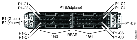
Figure 13. Locations, UPS connectors (rear)
MAP2740 Section-9 Flash enclosure power input problem (Model 983)
Procedure
-
Locate the storage enclosure power supply using the location code from the serviceable event
FRU list that sent you here. See Figure 14.
Figure 14. Location codes for storage enclosure (rear view) (Flash enclosure, 24 drive slots) 
-
Observe the failing storage enclosure power supply LEDs. See Figure 15.
Is the IN green LED lit?
- Yes. The failure is in the Flash enclosure. Exit this MAP and replace the next FRU in the FRU list.
- No. Go to step 3.
Figure 15. Location of the storage enclosure power supplies and LEDs (Model 983) 
-
Is the power cable connected and fully seated at the flash enclosure power supply and UPS? See
Table 4, Figure 14, Figure 15, and Figure 16.
- Yes. Go to step 4.
- No. Exit this MAP and select the flash enclosure power supply in the FRU list. When directed to replace it, connect the power cable.
Table 4. Flash enclosure power cables from UPS Storage module Flash enclosure Flash enclosure power input connector UPS UPS power output connector I1 F03 (upper) E1 (green) E61 (upper) J3 (green) I1 F03 (upper) E2 (yellow) E62 (lower) J3 (yellow) I1 F04 (lower) E1 (green) E61 (upper) J4 (green) I1 F04 (lower) E2 (yellow) E62 (lower) J4 (yellow) Figure 16. UPS output power cables to enclosures (rear)
Figure 17. Locations, UPS connectors (rear)