Exchange the power supply, 12V
Before you begin
 Use approved ESD procedures to prevent damage.
Attention:
- This procedure is not a stand-alone procedure. Customer disruption and damage to the hardware might occur when microcode and power boundaries are not in the proper conditions for this service action.
- If a serviceable event FRU repair directed you to this procedure, the microcode and power boundaries are already set.
- If a serviceable event FRU repair did not direct you to this procedure, see MAP1230 Replace a FRU without using a serviceable event.
Notes:
- All the cables and FRUs to be removed must be uniquely identified so they can be reinstalled correctly.
- If an installed earthquake resistance kit prevents you from accessing this FRU, refer to MAP1600.
DANGER
Hazardous
voltage, current, or energy levels are present inside of a component
to which this label is attached. (L001) 
Remove the power supply, 12V Section-1
Procedure
- Open the left rear cover. Remove the two screws
 that secure the right rear cover (trained
service personnel access area only).
that secure the right rear cover (trained
service personnel access area only).
Open the right rear cover. (Figure 1)Note: The screws must be reinstalled when the cover is closed to prevent customer access.Figure 1. Removing retaining screws on right rear machine cover 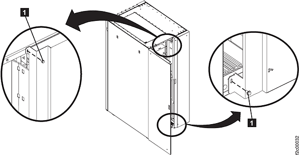
- Unfasten and then rotate all six power distribution
units (PDUs) away from the rear of the rack.
Figure 2. Power distribution units in normal position (rack rear view) 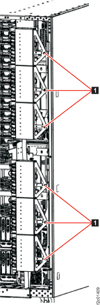
- Use two PDU service tools to hold the PDUs in the open
position. (Figure 3 and Figure 4).
- The PDU service brackets are stored in the Rack-1 front upper left documents enclosure.
- The upper three PDUs swing out as a group because they
are held together by a removable PDU alignment bracket.
The lower three PDUs are similar. - The PDU service tool should be installed on the middle PDU of each group of three.
- The PDU service tool bottom tab
 is inserted between the upper and
lower PDUs.
is inserted between the upper and
lower PDUs. - The PDU service tool fingers and
 straddle the PDU support bracket.
- Figure 4 shows the tool properly installed. The tool is delicate, do not put unnecessary force on the PDU group.
Figure 3. PDU service tool 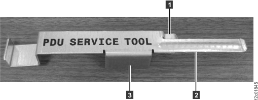
Figure 4. PDU service tool installed 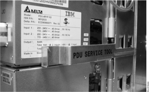
- A failure of this FRU is not isolated by code, it is only
isolated by a visual symptom.
- You should have been sent here by MAP2730 Visual symptoms for Ethernet switch tray (switches, fans, power junction assemblies) (Model 961) that isolated the problem to the power supply, 12V, as shown in Figure 5.
- This MAP repeats some of the isolation to ensure the correct power supply, 12V, is replaced.
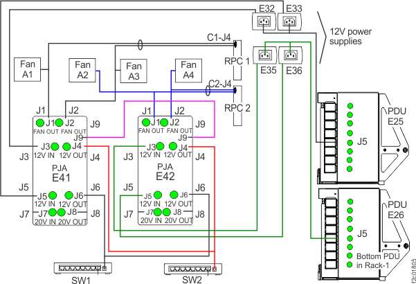
- There are four power supplies, 12V (E32, E33, E35, E36) that work in parallel to provide continuous power to the Ethernet switches and Ethernet tray fans.
- The power supplies are at the upper right rear of Rack-1.
- Each power supply receives power from a power distribution unit (PDU) at the rear of the rack.
Figure 5. Power supply, 12V (Ethernet switch tray fans, Ethernet switches) locations, rear upper right of rack 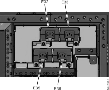
- Determine the correct power supply, 12V, to be replaced.
- At the rear of the rack on the Ethernet tray, locate both power junction assemblies (PJA), E41 and E42, as shown in Figure 6 and Figure 7.
- Observe the J3 and J5 LED indicators on both PJAs, as shown in Figure 6 and Figure 7.
- Use Table 1 to determine the LEDs condition and action.
Table 1. Power supply, 12V cables PJA E41-J3 input power LED PJA E41-J5 input power LED PJA E42-J3 input power LED PJA E42-J5 input power LED Action On On On On Not failing, exit this procedure. Off On On On Go to Remove the E32 power supply, 12V Section-2 On Off On On Go to Remove the E33 power supply, 12V Section-3 On On Off On Go to Remove the E35 power supply, 12V Section-4 On On On Off Go to Remove the E36 power supply, 12V Section-5 Off Off Off Off There are multiple failures. If there are no open related serviceable events, go to MAP2730 Visual symptoms for Ethernet switch tray (switches, fans, power junction assemblies) (Model 961). Figure 6. Ethernet switch tray locations (Model 961, rear of rack version 1) 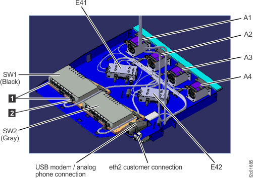
Figure 7. Ethernet switch tray locations (Model 961, rear of rack version 2) 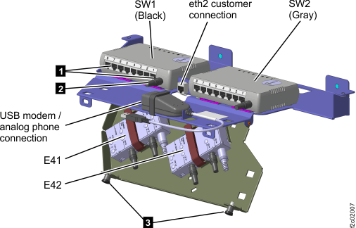
Figure 8. Power junction assembly (PJA) locations 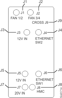
Remove the E32 power supply, 12V Section-2
Procedure
- Before replacing the power supply, ensure the problem is
not external to the power supply.
- Refer to Figure 9 for the E32 power supply.
- Ensure the PDU E25-J5 output power good LED indicator is lit. If it is off, do not replace the power supply, instead go to MAP2710 Power distribution unit (PDU) isolation (Models 961, 96E).
- Ensure the E32 power supply input cable is properly connected.
- Ensure the power supply cable is properly connected to the PDU E25-J5 connector.
- Ensure the power supply cable is properly connected to the PJA E41-J3 connector.
- If the cables are properly connected, go to the next step.
- If the cables are not properly connected, reconnect them now and then return to Remove the power supply, 12V Section-1, step 2.
Figure 9. Ethernet tray cabling